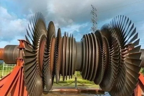

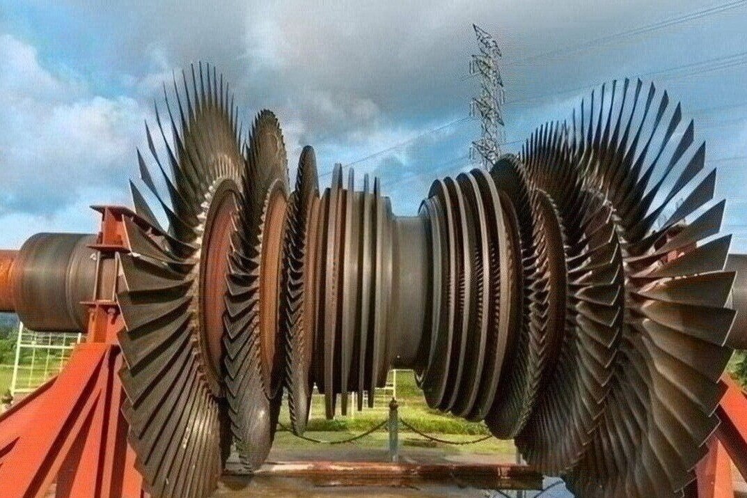
An aero engine blade is not merely a curved metal part: its airfoil, attachment, cooling features, coating, and tip geometry are designed for one stage, one load environment, and one service life. By the end, you will know how blades and vanes differ, why their manufacture demands more than accurate machining, and what evidence to request before approving a replacement or supplier.
Key takeaways
- Compressor blades add energy; turbine blades extract energy from combustion gas.
- Small clearance changes can alter efficiency, temperature, vibration, and blade life.
- Match materials and cooling systems to each stage’s temperature and loading.
- Choose manufacture, repair, or replacement after checking fit, damage, and qualification records.
Aero engine blades explained: anatomy and stage-by-stage function
Aero engine blades explained in practical terms: a blade is a rotating three-dimensional airfoil that adds or extracts work. Compressor blades add energy to incoming air; turbine blades extract energy from combustion gas. A vane is stationary, so it turns, accelerates, or diffuses flow without delivering shaft work.
- Airfoil: the curved section that creates the required pressure change and flow turning.
- Platform: the inner boundary that closes the annulus and controls leakage and secondary flow.
- Root: the attachment that transfers centrifugal load into the disk or rotor.
- Tip: the outer edge, which may include a shroud, squealer, or seal feature to limit clearance leakage.
| Section | Rotating blade function | Stationary vane function |
|---|---|---|
| Low-pressure compressor | Raises pressure and moves a large mass of air into the core or bypass system. Its broad passages prioritise flow capacity. | Straightens and diffuses air between rotor rows, recovering pressure before the next rotor. |
| Intermediate-pressure compressor | Adds further pressure rise after the low-pressure stages, with tighter incidence and loading control. | Sets the inlet angle and removes unwanted swirl before the next rotor. |
| High-pressure compressor | Produces the final compressor pressure rise before combustion, where small profile or clearance errors strongly affect stability. | Diffuses and turns air between closely loaded rotor stages, managing swirl and flow separation. |
| High-pressure turbine | Extracts the first, hottest portion of gas energy to drive the high-pressure compressor. Cooling passages, coatings, and specialised castings become critical. | Nozzle guide vanes accelerate and aim gas onto the rotor at the correct angle. |
| Intermediate-pressure turbine | Removes additional gas energy to drive the intermediate-pressure compressor. | Re-angles the gas for the next rotor while controlling expansion and residual swirl. |
| Low-pressure turbine | Extracts remaining useful energy to drive the low-pressure compressor, fan, or output shaft. | Directs gas into each succeeding rotor and helps complete expansion before the exhaust. |
Stage geometry is not interchangeable: stagger, thickness, tip shape, sweep, and stacking follow that stage’s pressure ratio, Mach number, temperature, and flow turning. That is why manufacturing aero-engine blades demands controlled airfoil machining or casting, accurate endwall geometry, and inspection beyond a nominal CAD outline.
Why geometry, loading, and clearance determine engine performance
A small change in metal angle, stagger, thickness, or three-dimensional sweep changes how a stage turns and accelerates flow. That changes pressure ratio and mass flow: excessive turning raises separation and loss, while insufficient turning leaves pressure recovery unused. Endwall shape and stacking matter too; an airfoil outline alone cannot preserve the intended flow field.
The loading distribution decides where aerodynamic work occurs along the chord and span. In a compressor, controlled loading adds shaft work to raise pressure; in a turbine, it extracts gas energy as turbine work. Poor loading increases fuel consumption for the same thrust or power and leaves a higher exhaust temperature.
Clearance is an operating loss, not merely a fit dimension. Tip gaps and seal gaps let air bypass the pressure difference, reducing compressor delivery and turbine work. Growth, rubs, and distortion can close that gap, causing vibration, rapid wear, or a rub that shortens engine life.
Design choices therefore have linked consequences:
- Geometry sets flow turning, pressure ratio, mass flow, and aerodynamic loss.
- Loading sets work extraction or addition, fuel demand, exhaust temperature, and stall margin.
- Clearance controls leakage, efficiency, vibration risk, and durability.
Cooling passages and film holes add another trade-off: they protect turbine metal but disturb the gas path. For gas turbine blade and vane manufacturers, reproducing these details requires controlled machining or casting, profile measurement, and traceable inspection. That is why aero engine blades matter: their geometry is a performance specification, not a decorative surface.
Materials and hot-section systems across gas turbine blade applications
Compressor parts operate in cooler air, where low density matters. Titanium alloys provide high specific strength in many compressor stages; nickel-based superalloys enter where pressure, temperature, or erosion risk rises. Turbine blades and vanes face far hotter gas, so nickel superalloys, oxidation-resistant coatings, and thermal barriers protect strength and surface condition.
Cooling is part of the airfoil design. Internal passages carry compressor bleed air through the blade, while film-cooling holes place a protective layer over selected hot surfaces. Their size and position affect metal temperature, cooling-air consumption, and aerodynamic loss.
| Sector | Material and cooling emphasis | Coating and construction consequence |
|---|---|---|
| Aircraft | Minimum mass, high cycle fatigue resistance, and tightly controlled internal cooling | Complex cast or machined thin sections; thermal-barrier and oxidation-resistant coatings where temperature demands them |
| Industrial aero-derivative | Aircraft-derived cores adapted to longer runs, starts, fuel variation, and repair targets | Coatings and wall thickness must support maintainability, inspection access, and repeated refurbishment |
| Marine | Corrosion resistance and tolerance of salt, humidity, and rapid load changes | Protective coatings and robust platforms or roots reduce damage from contaminated intake air |
| Power generation | Long exposure, high firing temperature, fuel contaminants, and creep resistance | Directionally solidified or single-crystal hot-section parts, advanced cooling, and repairable coating systems can justify higher complexity |
These differences explain why gas turbine blade applications cannot share one universal specification. A vane or blade sized for an aircraft duty cycle may fail economically in continuous service, while a heavier industrial construction can impose unacceptable mass in flight.
Specify the duty cycle, fuel and intake environment, temperature limits, coating system, and inspection method before comparing suppliers.
How manufacturers turn stage-specific design data into a qualified part
Aero engine blades explained only as nominal CAD surfaces are an incomplete manufacturing definition. Each stage needs its stacking coordinates, stagger, endwall blend, platform, tip clearance, section thickness, material condition, and, for hot parts, cooling passages and coating system.
Copying an airfoil outline can produce the wrong flow turning even when every scanned section appears accurate.
A qualified supplier proves the complete process chain, not access to a five-axis machine.
| Evidence | What it proves | Failure caught |
|---|---|---|
| Stage-controlled process plan | Workholding, datum scheme, tool paths, tool-life limits, and inspection points match the released configuration | Twist, runout, or stage-mismatched geometry |
| First-article report | CMM or optical results confirm sections, radii, platform, root, tip, and endwall geometry against tolerances | A conforming CAD surface with incorrect assembly features |
| Material and special-process records | Heat number, mill certificate, heat treatment, coating, cooling-hole, and repair records remain linked to the serial number | Untraceable alloy, coating, or thermal-processing variation |
| Nondestructive inspection | FPI, radiography, CT, or eddy-current testing addresses cracks, voids, blockage, and wall-thickness loss | Defects that dimensional inspection cannot see |
Ask gas turbine blade and vane manufacturers for a ballooned drawing, capability results, nonconformance dispositions, and serialized inspection data—not a screenshot of the model. Confirm that the inspection program measures the same datums used for machining.
For a supplier such as BVPL Turbine Parts, the useful question is whether those records follow each blade or vane through manufacture, inspection, repair limits, and release. That traceability demonstrates repeatability under production conditions.
Related products
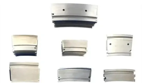
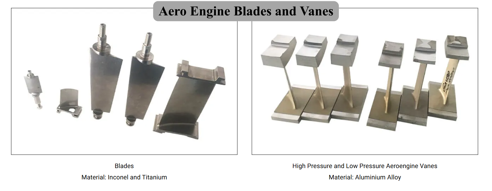 | Precision Components Manufacturer BVPL manufactures precision aero engine blades and vanes used in compressor and turbine stages of gas turbine engines. View product → |
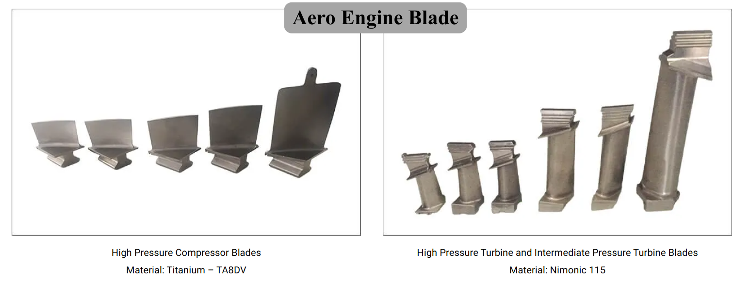 | Precision Components Manufacturer Aero Engine Blade View product → |
Fit, failure, and the decision between manufacture, repair, and replacement
Before ordering, match the part to the exact engine configuration, stage, and operating duty—not merely an airfoil drawing. Check these items:
- Confirm the part number, engine model, stage, left- or right-hand orientation, drawing revision, and modification status.
- Specify root, platform, shroud, tip-clearance, leading-edge, and trailing-edge limits, including datum references and allowable runout.
- Request material grade, heat-treatment condition, coating system, cooling-hole layout, wall-thickness limits, and any single-crystal or grain-orientation requirement.
- Require serialized material, dimensional, nondestructive-testing, coating, and first-article records, plus the approved repair limits.
Aero engine vane basics also matter: a stationary vane’s throat area, angle, and platform fit control the flow entering the next rotor. In gas turbine blade applications, a small profile error or blocked cooling passage can raise vibration, exhaust temperature, or local metal temperature even when the part appears acceptable by eye.
Inspection clues point toward different causes. Leading-edge dents and flattened profiles suggest foreign-object damage; tip rubs indicate clearance loss or rotor movement; fluorescent-penetrant cracks at platform corners or trailing edges indicate fatigue; oxidation, coating loss, blocked holes, and creep lean toward hot-section distress.
Use CMM or optical profile checks for shape, penetrant or eddy current for surface cracks, and radiography or computed tomography for internal defects.
A new part is the wrong solution when damage remains inside an approved repair envelope, the root or rotor is the real source of poor fit, or the replacement ignores an unresolved clearance, cooling, or operating-duty problem. Repair is worthwhile only with documented limits and a qualified process; otherwise, replace it.
Frequently asked questions
What is the difference between an aero engine blade and a vane?
A blade rotates and adds or extracts shaft work. A vane remains stationary and redirects, accelerates, or diffuses the gas flow.
Why do blade geometry, loading, and clearance affect gas turbine performance?
They control airflow, pressure rise or drop, efficiency, vibration, heat transfer, and the risk of rubbing or premature failure.
Which materials and hot-section systems are used for gas turbine blades?
Cold-section blades use alloys suited to lower temperatures, while hot-section blades use nickel-based superalloys with coatings, internal cooling passages, and film-cooling holes.
How do manufacturers qualify a gas turbine blade or vane?
They convert stage-specific design data into controlled drawings, material and process records, dimensional inspections, non-destructive testing, and acceptance documentation.
Should you manufacture, repair, or replace a damaged turbine blade?
Choose repair when approved limits and repair procedures preserve fit and performance; manufacture or replacement is safer when damage exceeds limits or traceability is incomplete.
Related products
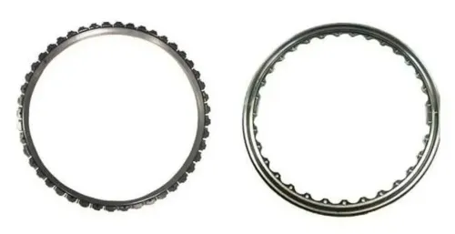
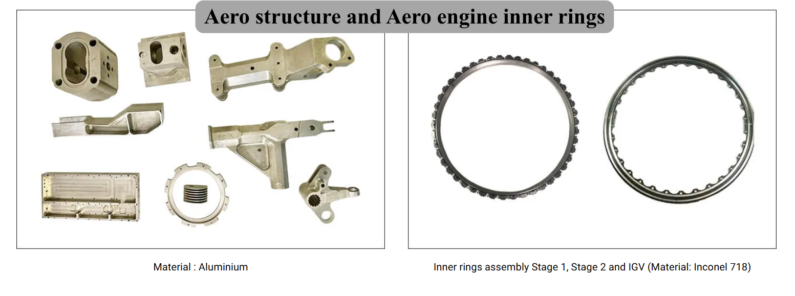 | Precision Components Manufacturer Aero structure and Aero engine inner rings BVPL Turbine Parts manufactures precision aero-structure components and aero engine inner rings used in critical aircraft and gas turbine assemblies. View product → |
 | Steam turbine components manufacturer Steam Turbine Blades and Vanes BVPL Turbine Parts manufactures precision steam turbine blades and vanes used in power generation turbines and industrial steam systems. View product → |