
A removed blade is not automatically a repair candidate: its identity, operating history, damage, material condition, and approved repair limits determine whether it returns to service, requires controlled restoration, or must be replaced. By following the recovery sequence from removal through inspection, engineering disposition, dimensional acceptance, and release documentation, you can separate a technically possible repair from an airworthy one.
Key takeaways
- Classify damage by location, depth, material, coating and cooling-feature impact.
- Reject recovery when cracks, distortion or material loss exceed approved repair limits.
- Verify fit with drawing dimensions, datum checks, root inspection and engine-specific records.
- Demand traceability, inspection results, repair details and release documentation with every blade.
What aero engine blade recovery means after removal
Aero engine blade recovery begins after removal and ends with an airworthy, traceable component—not simply an airfoil that looks repaired.
It differs from repair, which is one approved operation; refurbishment, which restores condition without necessarily addressing damage; overhaul, which follows a defined maintenance scope; replacement, which substitutes another approved part; and salvage, which cannot justify return to service.
The decision must account for operating history as well as the latest defect. Temperature excursions, creep, oxidation, erosion, foreign-object damage, and previous repairs can consume material capability beneath a visually acceptable surface. Aftermarket aero engine blade support therefore combines engineering review, inspection, approved repair planning, replacement manufacture, and release documentation.
1. Identify the engine model, module, stage, part number, serial or batch number, operating hours, flight cycles, and removal reason. Check life limits and prior repair records before any machining.
2. Record incoming condition and inspect the root, airfoil, platform, shroud, coating, and cooling features. Use dimensional measurement and calibrated nondestructive testing; appearance alone cannot establish acceptability.
3. Compare findings with the component maintenance manual, repair manual, service bulletin, or other approved data. Confirm that proposed blending, welding, coating work, or heat treatment has an authorized limit.
4. Return the blade to service after inspection, repair it within approved limits, or downgrade it only to another approved use.
5. Replace or scrap it when cracking, severe creep, oxidation, missing traceability, cumulative repairs, life limits, or dimensional loss exceed approved boundaries.
6. Issue records identifying the part, findings, operations, inspections, deviations, approved data, and release authorization.
How damage and inspection findings determine the recovery route
A cracked root, platform, or airfoil is not equivalent to a worn tip. Damage location, size, operating history, and approved limits determine whether the blade returns to service, enters repair, is downgraded, or becomes scrap.
Foreign-object damage, erosion, corrosion, oxidation, thermal fatigue, creep, tip rub, and repeated repairs can consume life even after visible damage is removed.
| Finding | Inspection method | Recovery consequence |
|---|---|---|
| Surface-breaking cracks | Fluorescent penetrant inspection; eddy-current inspection around conductive edges and holes | Crack location and length are compared with blend or repair limits; root cracking commonly rejects the blade |
| Internal or volumetric defects | Radiography for suitable internal conditions; ultrasonic testing where geometry and access permit | Indications can require engineering review or rejection; a clean surface does not prove internal soundness |
| Material loss and distortion | Airfoil scanning, coordinate measurement, root-datum fixtures, and visual inspection | Excessive thinning, creep, tip loss, or platform distortion can exceed restoration limits |
| Coating loss or damage | Visual examination, coating-thickness checks, and inspection after stripping | Acceptable loss may lead to stripping and recoating; substrate oxidation or cracking changes the disposition |
| Metallurgical damage | Metallographic review, hardness testing, and records of temperature exposure and repairs | Overheating, creep, or depleted material capability can prevent recovery despite acceptable dimensions |
These methods answer different questions: passing one does not establish dimensional accuracy, coating integrity, metallurgy, or remaining life. Effective turbine blade maintenance support therefore links calibrated NDT to traceable hours, cycles, distress history, and approved repair data. Aero engine blade recovery cannot extend a life limit without applicable approved data and supporting records.
Which repairs are acceptable for airfoils, roots, coatings, and cooling features
Only repairs permitted by current approved maintenance data are acceptable; technical feasibility alone does not make a recovered blade airworthy. The data—such as an engine or component repair manual, approved engineering instruction, or authority-accepted instruction—sets the repair zone, limits, process, heat treatment, inspection, and release evidence.
| Repair route | Approval controls | Hidden risk after machining |
|---|---|---|
| Controlled blending | Maximum depth, radius, and remaining wall thickness | Reduced fatigue margin or altered airfoil profile |
| Weld buildup | Qualified filler, heat input, shielding, preheat, and post-weld inspection | Porosity, lack of fusion, cracking, dilution, or heat-affected-zone damage |
| Laser or precision deposition | Qualified powder, layer thickness, thermal cycle, and final machining | Recrystallization or unacceptable microstructure, especially in directional or single-crystal alloys |
| Brazing | Approved alloy, joint clearance, furnace cycle, and location | Voids, weak joints, or blocked passages |
| Coating replacement | Approved strip, surface preparation, bond coat, thermal-barrier system, and thickness | Residual coating, poor adhesion, or excessive thickness |
| Cooling-hole restoration | Approved hole size, angle, position, edge condition, and cleaning method | Partial blockage, incorrect discharge direction, or thin ligaments |
Root, dovetail, fir-tree, shroud, and platform repairs receive separate scrutiny because unauthorized blending, plating, or buildup can change contact geometry and centrifugal-load distribution. Many instructions allow airfoil work while prohibiting attachment-surface changes.
Effective turbine blade maintenance support uses dedicated fixtures, root datums, coordinate measurement, controlled welding, coating-strip capability, and calibrated NDT. Records must link each operation to the approved data. That discipline protects precision aero engine components from defects machining cannot reveal.
How to prove a recovered or replacement blade will fit
A recovered or replacement blade fits only when its records and measured features agree with the engine or component maintenance data—not when it resembles a generic drawing. The acceptance decision must cover the complete part identity, configuration, and approved repair limits.
1. Match the part number, dash number, serial or batch identity, engine model, module, stage, and blade position. Confirm operating hours, flight cycles, life limit, and previous repairs; a technically sound part cannot be accepted if its life history is incomplete.
2. Compare measured geometry with the controlled definition: airfoil section coordinates, chord, thickness, leading- and trailing-edge radii, twist, platform dimensions, tip clearance, shroud fit, and radial or axial runout. Check throat area and adjacent-blade relationship, because a local dimension can pass while the assembled stage flows incorrectly.
3. Verify the attachment against the specified root form, including fir-tree or dovetail dimensions, serrations, contact faces, platform fit, and retention features. Confirm the material grade, heat treatment, coating system and thickness, surface condition, cooling-hole locations, diameters, masking, and flow results.
4. Check mass properties and balance against the stage or rotor requirement, then review inspection evidence from calibrated coordinate measurement, dimensional gauges, and applicable nondestructive testing. The release package must cite the current repair manual, approved engineering instruction, or other accepted maintenance data used for aero engine blade recovery.
A generic blade drawing rarely states coating-strip allowances, cooling-flow limits, repair-cycle restrictions, or stage balance criteria. Manufacturers of precision aero engine components need controlled fixtures, repeatable machining, and traceable measurements to prove those details—not merely produce a blade that looks right.
What a manufacturer must deliver with recovered blades
A recovered blade is not ready for installation because its airfoil now matches a drawing. The manufacturer must show that the root, platform, airfoil, coating, cooling features, and balance remain within approved limits, using repeatable tooling rather than freehand rework.
Soft and hard fixtures, root datums, coordinate measurement or airfoil scanning, controlled deposition equipment, coating-strip facilities, and calibrated NDT prevent one repaired section from losing alignment with the rest of the assembly.
Ask for a recovery package containing:
- Part number, serial or batch identity, engine model, module, stage, operating hours, cycles, and removal reason
- Incoming photographs and condition report, including prior repairs and coating state
- Dimensional results tied to defined datums, not isolated readings
- NDT records identifying the method, equipment, calibration status, indications, and disposition
- Material, heat-treatment, welding or deposition, coating, and cooling-hole records
- Approved maintenance data, repair limits, deviations, and authorized release-to-service documentation
For aftermarket aero engine blade support, BVPL Turbine Parts can be assessed on whether its records support the installation decision, not merely whether it can make or restore a blade.
| Decision | Repair is defensible when | Replacement is defensible when |
|---|---|---|
| Repair | Damage falls within approved limits; traceability is complete; inspection proves remaining life and geometry | Not applicable |
| Replace | Repair would require multiple operations, life or dimensional limits are exhausted, or records are incomplete | New or serviceable supply offers the lower-risk route |
| Reject | Root cracking, severe creep, oxidation, or unapproved damage remains | Scrap or quarantine is required; technical feasibility does not create approval |
Related products
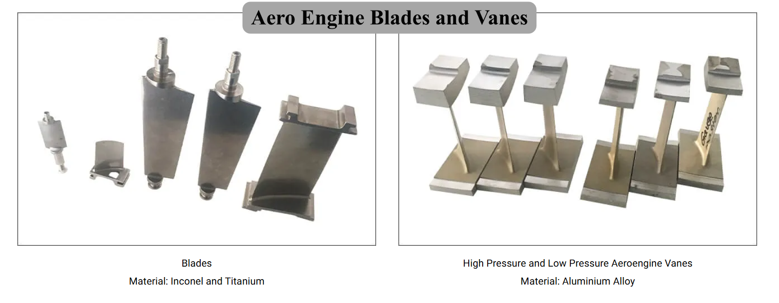 | Precision Components Manufacturer BVPL manufactures precision aero engine blades and vanes used in compressor and turbine stages of gas turbine engines. View product → |
 | Precision Components Manufacturer BVPL manufactures precision aero engine blades used in compressor and turbine stages of gas turbine engines. View product → |
Frequently asked questions
What does aero engine blade recovery involve after removal?
Recovery involves receiving and identifying the removed blade, inspecting its airfoil, root, coating and cooling features, selecting an approved repair or replacement route, completing dimensional and non-destructive inspections, and issuing traceable release records.
How do damage findings determine the recovery route?
The route depends on the damage type, location, depth, size, material condition and effect on cooling or load-bearing features. Findings such as cracks, erosion, oxidation, tip loss, platform damage or root wear must be compared with the applicable repair limits.
Which blade features require special attention during repair?
Airfoils, roots, platforms, coatings, tip regions and cooling holes each have different acceptance concerns. Repairs must preserve airfoil geometry, root fit, coating integrity, cooling-flow characteristics and required surface condition.
How can you prove a recovered or replacement blade will fit?
Use the approved part number and configuration, inspect critical drawing dimensions and datums, check root and platform geometry, confirm airfoil profile, and compare the component records with the engine or module requirements.
What records should accompany recovered aero engine blades?
Request identification and batch details, inspection findings, non-destructive testing results, repair process and materials, dimensional reports, coating records, heat-treatment information when applicable, and the authorised release or conformity documentation.
Related products
 | Steam turbine components manufacturer Steam Turbine Blades and Vanes BVPL Turbine Parts manufactures precision steam turbine blades and vanes used in power generation turbines and industrial steam systems. View product → |
 | 1. Industrial Gas Turbine Shrouds, Shroud Shoe Tiles, Nozzles and Diaphragms Industrial Gas Turbine Shrouds BVPL Turbine Parts manufactures precision industrial gas turbine shrouds, shroud shoe tiles, nozzles and diaphragms designed to improve turbine... View product → |
 | Gas turbine components manufacturer Industrial Gas Turbine Shrouds, Shroud Shoe Tiles, Nozzles and Diaphragms BVPL Turbine Parts manufactures precision industrial gas turbine shrouds, shroud shoe tiles, nozzles and diaphragms designed to improve turbine... View product → |
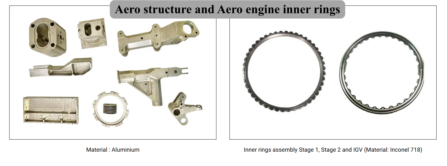 | Precision Components Manufacturer Aero structure and Aero engine inner rings BVPL Turbine Parts manufactures precision aero-structure components and aero engine inner rings used in critical aircraft and gas turbine assemblies. View product → |