
A Nimonic 115 blade is valuable only when its temperature capability, creep life, geometry and manufacturing route match the engine stage. By the end, you will be able to compare its service advantages with competing materials, distinguish HPT from IPT requirements, and check whether a proposed replacement has the evidence and dimensions needed for safe installation.
Key takeaways
- Gamma-prime strengthening supports creep and stress-rupture resistance near 870 °C.
- Match Nimonic 115 to pressure stage, cooling design, geometry, and operating temperature.
- Compare material data with the blade’s actual load, coating, and manufacturing route.
- Require traceability, inspection records, and test evidence from your high-pressure turbine blade supplier.
Which Nimonic 115 blade benefits matter at operating temperature?
At approximately 870 °C, Nimonic 115 retains useful strength because aluminium and titanium form gamma-prime precipitates that resist dislocation movement. That strengthens a blade against centrifugal load and gas bending while supporting creep and stress-rupture resistance, fatigue performance, and resistance to permanent deformation during long exposure.
Oxidation resistance adds protection, but it does not make the alloy immune to damage.
Treat 870 °C as a commonly cited service ceiling for the alloy, not a gas-temperature limit. Compare the actual blade-metal temperature, stress, exposure time, cooling effectiveness, coating condition and required life; a hotter gas stream can produce a lower metal temperature, while blocked cooling holes can reverse that result.
The key Nimonic 115 blade benefits matter only when the complete stage design supports them.
- Request temperature-dependent tensile data and allowable stress tables covering the intended metal-temperature range.
- Request creep-rupture curves that state test temperature, applied stress and duration.
- Request oxidation results identifying temperature, atmosphere, exposure time, specimen condition and coating system.
- Request fatigue data identifying thermal-mechanical or rotating-bending conditions, cycle count and dwell time.
| Evidence | What to check | Why it matters |
|---|---|---|
| Metal temperature | Peak, steady-state and transient maps | Determines usable strength and creep margin |
| Surface protection | Coating condition, deposits and cooling-hole cleanliness | Oxidation, hot corrosion and sulphidation can accelerate failure |
| Operating duty | Fuel chemistry, start-stop cycles and dwell periods | Erosion, thermal fatigue and stress history change life |
| Load history | Centrifugal and gas-bending stress against allowable values | Prevents strength data from being used outside its design basis |
Why HPT and IPT blades do not face the same material decision
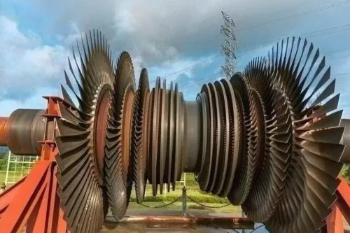
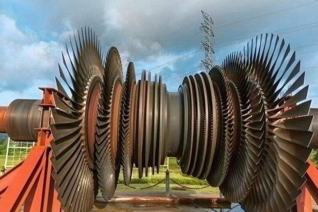
HPT blades sit closest to the combustor, where high inlet-gas and metal temperatures combine with steep thermal gradients, high rotational speed, centrifugal stress, gas-bending load and cooling-hole stress concentrations. Nimonic 115 makes sense when its creep strength and hot-section life outweigh its greater density and the resulting rotating mass.
| Stage | Dominant design question | Material implication |
|---|---|---|
| HPT | Can the blade survive peak metal temperature, sustained stress and thermal gradients? | Nimonic 115 is attractive when creep, stress rupture and oxidation margins justify its density. |
| IPT | What temperature, pressure ratio, speed and dwell time does this engine architecture impose? | A nickel alloy may fit, but a lighter or lower-cost alloy can win in a materially cooler stage. |
| Both | Will deposits, corrosive chemistry and repeated transients damage the surface? | Assess protection separately from bulk strength. |
Do not treat “intermediate pressure turbine blades” as an automatic Nimonic 115 application. IPT conditions vary with spool arrangement, expansion ratio, cooling scheme and engine duty; stage name alone cannot establish the required creep margin.
Separate the damage mechanisms before choosing:
- Oxidation attacks exposed alloy at high temperature.
- Hot corrosion and sulphidation depend on fuel chemistry, salts and deposits.
- Deposit attack can block cooling holes and alter local heat transfer.
- Thermal cycling drives cracking through repeated temperature gradients.
Compare the complete stage condition: metal-temperature maps, rotational speed, dwell time, stress margin, expected cycles and inspection interval. Tensile strength alone misses the density penalty in HPT service and the possibility that a cooler IPT stage gains little from an expensive nickel superalloy.
How geometry, cooling and manufacturing route determine the real benefit
A blade with perfect Nimonic 115 chemistry can still fail if its geometry creates a hot spot or stress concentration. Airfoil wall thickness, leading-edge radius, trailing-edge cooling, film-cooling hole diameter and position, internal passage layout, tip clearance, squealer tip, shrouds, platforms and root fillets all change local temperature, strain and centrifugal stress.
Coatings are system choices, not automatic upgrades. A thermal-barrier, bond or internal coating must be assessed for diffusion into Nimonic 115, thermal-expansion mismatch, bond-coat behaviour, cooling-hole blockage, surface preparation and repair stripping. A coating that improves oxidation life can still reduce cooling flow or complicate refurbishment.
Product form changes what the alloy can safely do:
| Route | Grain structure and creep behaviour | Practical consequence |
|---|---|---|
| Wrought | Worked, generally equiaxed grains; lower directional creep advantage | Consistent stock, but machining allowance and ultrasonic access require control |
| Forged | Refined flow and grain structure around the component | Strong root and fillet potential; inspect forging quality and residual stress |
| Conventionally cast | Equiaxed grains with casting defects to control | Complex passages are feasible; porosity, fatigue life and repair access demand scrutiny |
| Directionally solidified | Aligned grains reduce transverse creep weakness | Better creep anisotropy control, but higher process complexity and inspection demands |
Machining Nimonic 115 requires rigid fixturing, controlled cutting parameters and tooling that resists work hardening and heat retention from low thermal conductivity. Inspect edges, holes, fillets and platforms for tears, laps, burrs, recast material and excessive thinning; each can initiate fatigue. Repairability and inspection access belong in the route decision, not after delivery.
How Nimonic 115 compares with other hot-section materials
Nimonic 115 is not automatically the best hot-section material. Its density increases rotating mass and centrifugal load, so its Nimonic 115 blade benefits earn their cost only when metal temperature, creep-rupture life and sustained strength exceed what lighter or more easily processed materials can deliver.
| Option | Advantage | Limitation and best fit |
|---|---|---|
| Nimonic 90 | Related nickel superalloy for high-temperature strength | Select against the required temperature capability, strength, product specification and life; do not assume interchangeability with Nimonic 115 |
| Inconel 718 | Strong, widely available and comparatively manufacturable | Better suited to lower-temperature or shorter hot-section exposure than the long-duration envelope demanded by the hottest blades |
| René alloys | Modern nickel-base options with higher temperature or creep capability | Higher cost, complex processing and tighter supply can outweigh the performance gain |
| Ceramic-matrix composites | Far lower density and exceptional temperature potential | Brittle behaviour, impact sensitivity, environmental-barrier-coating dependence, and different inspection and repair methods |
Nimonic 90 may suit a cooler stage or a specification that does not justify Nimonic 115. An intermediate-pressure turbine blade is not automatically a Nimonic 115 application: engine architecture determines its metal temperature, stress and dwell time. CMCs also require a different design and maintenance system, not a direct metal replacement.
Score each candidate against:
- Actual metal temperature and creep-rupture life
- Fatigue cycles, density and centrifugal-load margin
- Coating system, environmental attack and cooling design
- Manufacturability, inspection access and repair route
- Total lifecycle cost, including rejected parts and coating maintenance
What a high-pressure turbine blade supplier must prove before delivery
A high pressure turbine blade supplier must prove both metallurgical condition and finished-part conformity; “Nimonic 115” alone does not establish interchangeability. Request a numbered evidence pack before accepting blades for an HPT or intermediate pressure turbine blades application.
1. Request the material certificate naming the applicable specification, heat number, product form, chemical results, heat-treatment cycle, hardness or tensile results, and complete traceability from melt through machining.
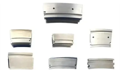
2. Require a dimensional inspection report covering airfoil profile, wall thickness, root or fir-tree geometry, platform dimensions, fillets, surface finish, and critical tolerances. Include cooling-passage dimensions and every cooling-hole position, diameter, angle, and orientation.
3. Check non-destructive testing results against the product form. Penetrant examination finds surface-breaking cracks and porosity; ultrasonic examination applies to suitable wrought stock or forgings and detects internal discontinuities. Request metallography when the governing specification calls for grain structure, precipitate condition, or repair assessment.
4. Demand coating records identifying surface preparation, coating system, batch, thickness or process controls, inspection results, and any stripping or recoating. Obtain signed conformity documentation linking each result to the blade serial number.
5. Treat weld repair as a separate qualification issue. The procedure must cover the exact defect, section thickness, heat input, liquation cracking, strain-age cracking, filler, post-weld treatment, and inspection method.
6. Confirm engine model, stage number, part number, airfoil profile, root geometry, platform dimensions, balance requirements, and coating specification before release. BVPL Turbine Parts can add value by connecting alloy certification with controlled machining, geometry, coating, and inspection records.
Related service
Aero Engine Blade High Pressure Turbine and Intermediate Pressure Turbine Blades Material: Nimonic 115 High Pressure & Intermediate Pressure Turbine Blades Material: Nimonic 115 Nimonic 115 is a high-performance nickel-chromium-cobalt alloy engineered... |
Frequently asked questions
What are the main Nimonic 115 blade benefits at operating temperature?
At approximately 870 °C, aluminium- and titanium-based gamma-prime precipitates resist dislocation movement. This supports strength under centrifugal and gas-bending loads, along with creep, stress-rupture, fatigue, and deformation resistance.
Why do HPT and IPT blades need different material decisions?
High-pressure turbine blades face hotter gas and severe centrifugal loading, while intermediate-pressure turbine blades operate in a different temperature and load environment. Select the alloy against each stage’s temperature, stress, cooling arrangement, and duty cycle.
How do geometry, cooling, and manufacturing route affect Nimonic 115 performance?
They determine the stresses, metal temperature, wall thickness, cooling effectiveness, and defect risks the blade experiences. Evaluate the complete design and production route rather than treating the alloy name as a performance guarantee.
What should a high-pressure turbine blade supplier prove before delivery?
Request material identity and heat or batch traceability, dimensional inspection results, non-destructive examination records, heat-treatment details, and evidence that the finished blade meets the agreed drawing and specification.