
A pressure vane is usually a compressor stator or guide vane, not a turbine hot-section vane, and “high pressure” or “low pressure” describes its engine stage rather than a universal material choice. By following the material decision, machining route, inspection evidence, and fit checks, you can judge whether an aluminium vane is suitable for an existing assembly and whether its supplier can prove conformity.
Key takeaways
- Confirm the vane’s compressor location before comparing materials or suppliers.
- Request the alloy designation, temper, heat-treatment record, and full material traceability.
- Ask how the supplier supports thin airfoils during machining and finishing.
- Require dimensional, surface, and non-destructive inspection records before acceptance.
What a pressure vane is—and where aluminium belongs
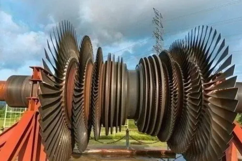
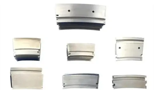
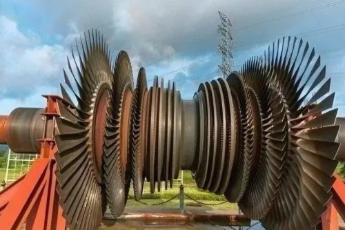
A pressure vane is usually a fixed compressor airfoil: a stator vane or guide vane positioned between rotating compressor blades, or at the inlet, to straighten, turn, or control airflow. It is not interchangeable with every engine vane.
High pressure and low pressure vanes belong to different compressor spools or stages and face different aerodynamic, thermal, and stress demands.
| Location | Operating duty | Material implication |
|---|---|---|
| High-pressure compressor | Higher pressure, temperature, aerodynamic loading, and tighter stress limits | Aluminium requires specific qualification and temperature evidence |
| Low-pressure or inlet compressor | Cooler airflow and lower local loading | Aluminium is more likely to be suitable when stress and temperature limits permit |
| Turbine hot section | High temperature, oxidation, erosion, and centrifugal loading | Nickel, cobalt, titanium, stainless-steel, or ceramic systems are normally specified |
Aluminium aero engine vanes gain from low density and efficient machining, which reduce mass and cutting effort. Corrosion resistance, fatigue life, strength retention, and service-temperature capability depend on the exact alloy and temper, not on the word “aluminium.” A wrought alloy such as 2618 may suit an elevated-temperature compressor application; generic 6061 cannot be assumed.
Aluminium alloy turbine vanes are generally the wrong choice for hot sections.
Specify the alloy, product form, temper, heat-treatment condition, allowable properties, conductivity, and service-temperature limit in the purchase specification. Do not select material from “high pressure,” “low pressure,” “turbine,” or a supplier phrase such as aero engine parts manufacturers aluminium pressure vanes in Singapore alone.
How the approved material becomes a near-net-shape vane
Start with the drawing and specification review, not the machine. Confirm the part number and revision, alloy, temper, product form, datums, airfoil coordinates, platform, shroud, root, holes, edge radii, coating, and permissible tolerances.
Record the material certificate against the melt, billet, or forging heat number; a nominal alloy certificate alone does not prove lot identity or process history.
A controlled wrought blank or near-net-shape forging normally replaces a large oversized block. Forging can align grain flow and reduce machining time, but die mismatch, flash removal, contour variation, and residual stress must be controlled before final inspection.
Use a documented route:
- Prepare the billet or forging, preserve identification, and design a fixture that supports the root and platform without marking airfoil surfaces.
- Rough and semi-finish the pressure and suction surfaces, platform, shroud, root, mounting features, and specified internal or leading-edge geometry.
- Apply stress relief where specified, then perform low-stock finishing, drilling, deburring, heat treatment, surface treatment, and coating.
- Balance the component if required, inspect it, and issue release documentation linking every operation to the heat number.
CNC milling, especially five-axis machining, keeps the cutter near normal to changing airfoil surfaces and reduces gouging or excessive cutter engagement. Acceptance rests on section coordinates, datum relationships, edge geometry, and drawing tolerances—not a generic “five-axis accuracy” claim.
That discipline defines reliable aluminium aero engine vanes for aero engine parts manufacturers aluminium pressure vanes in Singapore.
How manufacturers protect thin airfoils during machining and finishing
A thin airfoil can leave the machine with the wrong camber or twist even when its dimensions look close. Removing material from one side releases residual stress and lets the pressure and suction surfaces move, so manufacturers protect aluminium aero engine vanes through controlled, staged machining.
1. Fixture the platform and root firmly without marking either airfoil surface. Use balanced stock removal, stable roughing, and staged semi-finishing; leave a separate low-stock final pass. Chatter creates waviness, tool deflection shifts coordinates, and heat buildup softens or distorts the cut.
2. Control the edges as engineered features. Define handling and blending limits for the leading and trailing edges: burrs can damage a trailing edge, cutter breakout changes its radius, and aggressive hand blending changes camber or twist. Drill mounting holes from controlled datums, then remove burrs without enlarging the holes or moving their positions.
3. Treat heat treatment as dimensional control as well as strengthening. Solution treatment, quenching, and artificial ageing can cause distortion, residual stress, hardness changes, and conductivity changes. Tie the process specification, such as AMS 2770 for wrought aluminium, to the exact alloy and temper, then recheck critical geometry.
4. Apply anodizing or chemical conversion coating only to the specified system. Control masking, coating thickness, sealing, roughness, electrical properties, and fatigue effects. Shot peening is not automatic: specify intensity, media, coverage, and masked zones, because a thin aluminium alloy turbine vane can distort or become rougher.
How inspection proves the vane is the right shape, material, and condition
Acceptance requires evidence, not appearance. A vane can look smooth and still fail its airfoil profile, alloy temper, hole location, or installation clearance.
1. Measure the controlled geometry. Use a CMM or optical scanner against the approved CAD model and drawing datums to verify airfoil-section coordinates, camber, twist, platform and root dimensions, shroud location, hole pattern, edge radii, and mating clearances. Use profile gauges for quick section checks, then record dimensional inspection results.
2. Check the surface. Measure roughness because a polished-looking surface can still contain waviness outside profile tolerance. Inspect for cracks, dents, burrs, cutter breakout, and harmful blending at the leading and trailing edges.
3. Select NDT by material and indication. Dye-penetrant inspection under ASTM E1417/E1417M can reveal open-to-surface cracks and laps where the geometry and specification permit. Magnetic-particle inspection is not the default for non-ferromagnetic aluminium. Eddy-current inspection requires defined probe frequency, lift-off, geometry, calibration standard, coverage, and acceptance criteria.
4. Verify material condition. Perform hardness or conductivity checks when specified, and review the material certificate, heat-treatment and coating records, first-article inspection, and traceability from heat number through final release. Require a certificate of conformity.
5. Reject out-of-tolerance coordinates, twist, camber, waviness, cracks, dents, burrs, incorrect hole position, wrong handedness, incorrect temper, or traceability gaps through documented disposition—not informal blending. For reverse engineering, verify datums, reconstruct aerodynamic intent, define tolerances, and obtain engineering approval before flight or power-generation use.
How to select and verify a supplier before accepting the quotation
Reject any quotation that cannot identify the controlled drawing revision, alloy and temper, heat-treatment records, permissible tolerances, inspection plan, first-article requirements, batch traceability, coating specification, approved subcontractors, certificate of conformity, export documentation, and configuration-control process.
Ask the aero engine vane manufacturer in Singapore:
- How do you control CNC programming, fixture design, inspection setup, nonconforming-part rework, and communication with OEM or MRO engineering teams?
- Which material families, maximum qualified service temperatures, forging and heat-treatment processes, NDT methods, and representative first-article records can you provide?
- Which special processes hold accreditation? NADCAP accreditation applies to named processes, not every operation at the facility.
For an existing assembly, match the part number and revision, datum scheme, root and platform dimensions, mounting-hole pattern, handedness, airfoil orientation, mating surfaces, and installation clearances. Do not approve a replacement from an external scan alone.
| Material | Mass and machining | Temperature, loading, and life |
|---|---|---|
| Aluminium | Lowest mass; easiest machining; lowest cost | Cooler service; limited strength retention, erosion resistance, and service life |
| Titanium | Low mass; harder machining; higher cost | Higher temperature and strength; good erosion resistance |
| Stainless steel | Heavier; moderate machinability and cost | Better corrosion and temperature capability than aluminium |
| Nickel alloy | Heaviest; difficult machining; highest cost | Hot sections, oxidation, centrifugal loading, and long service life |
Aluminium is wrong for a hot turbine location, severe oxidation or erosion, high centrifugal loading, or a design approved for another alloy. This distinction matters when comparing aero engine parts manufacturers aluminium pressure vanes in Singapore: “aluminium alloy turbine vanes” may actually mean compressor vanes.
BVPL Turbine Parts belongs in the comparison only when its documented processes match the specific requirement.
Related items
Aero Engine Blades and Vanes High Pressure and Low Pressure Aeroengine Vanes Material: Aluminium Alloy High Pressure and Low Pressure Aeroengine Vanes Material: Aluminium Alloy |
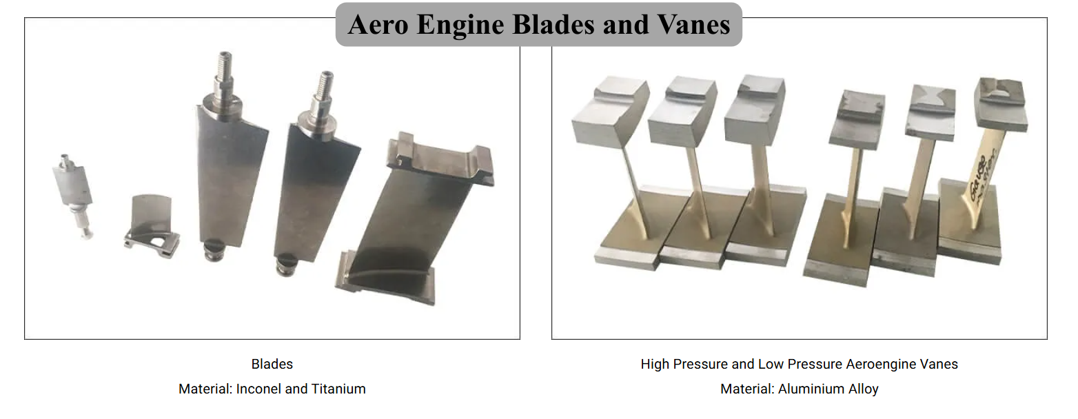 | Precision Components Manufacturer BVPL manufactures precision aero engine blades and vanes used in compressor and turbine stages of gas turbine engines. View product → |
Frequently asked questions
What is an aluminium pressure vane?
It is a fixed compressor airfoil, such as a stator or guide vane, that straightens, turns, or controls airflow. It is not interchangeable with every engine vane.
How does an approved aluminium alloy become a pressure vane?
The manufacturer verifies the alloy and condition, produces a near-net blank, then uses controlled CNC machining, finishing, and inspection to achieve the vane’s aerodynamic and dimensional requirements.
How do manufacturers prevent damage to thin aluminium airfoils?
They use suitable workholding, controlled cutting loads, sharp tooling, stable machining sequences, and careful deburring and finishing so the airfoil does not distort, gouge, or lose its edge profile.
What should you verify before accepting an aero-engine vane supplier’s quotation?
Check the exact vane location, drawing revision, alloy and temper, heat-treatment records, inspection plan, traceability documents, delivery assumptions, and the supplier’s experience with thin precision airfoils.