
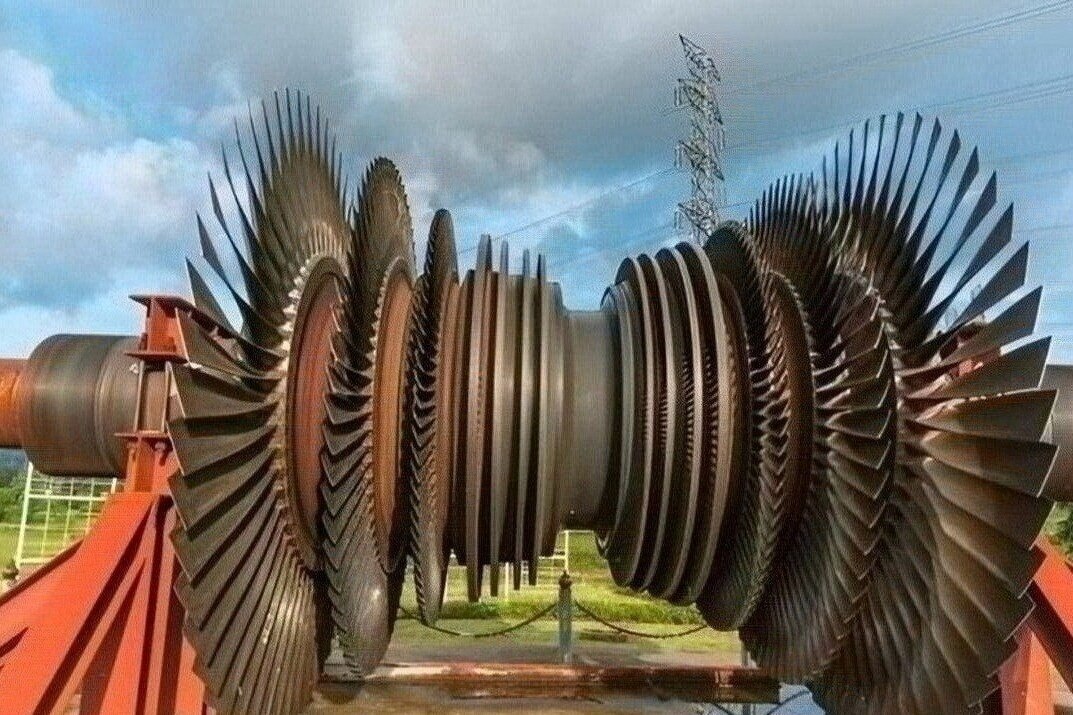
Selecting a supplier for Nimonic 115 turbine hardware requires more than confirming that a company machines nickel alloys. You will be able to verify the material condition, distinguish high-pressure from intermediate-pressure duty, compare manufacturing routes, and assemble the technical records needed before requesting a quotation.
Key takeaways
- Confirm Nimonic 115 grade, heat treatment, and material condition before comparing suppliers.
- Match blade or vane location to pressure, temperature, and known failure modes.
- Request dimensional, material, coating, and non-destructive inspection evidence.
- Send drawings, operating data, specifications, and acceptance criteria in one technical package.
Confirm the Nimonic 115 material condition before comparing suppliers
A drawing callout for Nimonic 115 identifies a specific precipitation-strengthened nickel-base wrought alloy, not a generic name for every nickel superalloy. Before comparing gas turbine blade and vane manufacturers, verify the material condition tied to the part; “Nimonic aero engine components” does not establish interchangeability.
1. Request the exact alloy designation, product form, chemistry limits, governing material specification, heat-treatment condition, and applicable customer requirements. “Nimonic 115” without its form and specification is incomplete.
2. Require heat-lot traceability from the certificate to the supplied material, plus chemical analysis, mechanical-test results at the relevant temperature, heat-treatment charts, and grain-size or microstructure records.
3. Confirm that the evidence covers the finished part or defined batch and includes dimensional inspection, coating records where applicable, and non-destructive testing. A material certificate alone does not prove suitability for Nimonic 115 turbine blades unless it identifies the heat, form, condition, and specification tied to those blades.
Nimonic 115’s high aluminium and titanium content forms a substantial gamma-prime strengthening phase. That chemistry improves high-temperature strength but increases cutting forces, work-hardening risk, tool wear, weld-cracking risk, and heat-treatment sensitivity.
For any repair or welded feature, request an approved procedure covering filler selection, preheat or interpass control, post-weld heat treatment, and non-destructive inspection. Generic TIG capability is not enough evidence for this alloy.
Match Nimonic 115 to the pressure section and failure modes
Do not assign Nimonic 115 to a pressure section from exhaust-gas temperature alone. Judge the blade’s metal temperature, pressure loading, rotational speed, stress level, dwell time, low-cycle fatigue, root fatigue, coating compatibility, and required life.
| Pressure section | Temperature and pressure | Mechanical and environmental demands | Cooling and life exposure |
|---|---|---|---|
| High pressure turbine blades | Highest gas-path temperature and pressure | Highest centrifugal loading; severe vibration, oxidation, erosion, creep, and stress-rupture exposure | Cooling air is limited by compressor bleed cost; metal-temperature control and dwell-fatigue life dominate |
| Intermediate pressure turbine blades | Lower temperature and pressure than HPT service, but stage-specific | Centrifugal stress remains high; vibration, erosion, oxidation, and root fatigue can govern | Cooling demand may be lower, but longer dwell and different vibratory modes can change the life calculation |
Use the table as a duty comparison, not a material approval. A wrought Nimonic 115 specification is not automatically interchangeable with a single-crystal HPT design: grain-boundary behaviour, crystal orientation, cooling-hole geometry, and approved repairs are design-specific.
Benchmark the selection against:
- Nimonic 90, where established wrought capability and lower-duty requirements may fit.
- Inconel 939 or Rene 80, where casting route, oxidation resistance, or creep capability changes the trade-off.
- Directionally solidified or single-crystal nickel superalloys, where removing transverse grain boundaries supports demanding HPT life.
Nimonic 115 turbine blades may fit an intermediate-pressure application yet fail an HPT life target through creep, stress rupture, dwell fatigue, coating degradation, or root fatigue. Confirm the required life against measured metal temperature and stress history, not the exhaust-gas reading or alloy name.
Compare manufacturing routes, blade features, and inspection evidence
Require the supplier to identify whether the airfoil starts as bar, forging, investment casting, powder metallurgy, directionally solidified material, or a single-crystal route. These choices change grain structure, creep resistance, buy-to-fly ratio, and geometry limits.
For gas turbine blade and vane manufacturers serving Nimonic 115 engine applications, the capability review must cover the airfoil section, platform, root attachment, shroud, tip geometry, cooling passages, and film-cooling holes.
| Route | Main advantage | Main risk or limit |
|---|---|---|
| Bar or forging | Strong traceability and wrought grain structure; suitable for many Nimonic aero engine components | Five-axis cutting causes work hardening, tool wear, and local heat concentration |
| Investment casting | Complex airfoils and internal cooling passages with less machining | Inclusions, shrinkage, hot tears, and dimensional variation require control |
| Powder metallurgy | Fine, uniform material for selected geometries | Powder quality, consolidation, and allowable geometry require qualification |
| Directionally solidified | Reduced transverse grain boundaries and improved creep performance | Orientation and casting controls restrict design freedom |
| Single crystal | No grain boundaries across the principal stress direction | Crystal orientation, cooling geometry, and repair approval are design-specific |
Define inspection evidence for every route:
- Use coordinate measurement for airfoil, platform, root, shroud, and tip dimensions.
- Use radiography or computed tomography for inclusions, shrinkage, and internal passages; use borescopy where access permits.
- Flow-test each cooling circuit and record blockage, flow distribution, and pressure loss limits.
- Verify EDM-hole diameter and position, then check surface finish and film-hole condition against the drawing.
Use a capability-based supplier comparison instead of a material keyword
A qualified supplier proves a process route, not just an alloy listing. For gas turbine blade and vane manufacturers, Nimonic 115 engine applications require evidence that matches the part’s geometry, pressure section, and production status. Ask specifically about high pressure turbine blades rather than accepting a general aerospace capability statement.
| Capability | Evidence to request |
|---|---|
| Dimensional capability | CMM results, tolerances, airfoil and root measurement capability |
| Five-axis CNC machining | Proven programs for thin airfoils, platforms, roots, and tips |
| Forging or investment casting | Route, tooling, grain structure, defect controls, and buy-to-fly data |
| EDM | Controlled recast layer, taper, burr removal, and hole-position inspection |
| Cooling-hole drilling | Laser or EDM parameters, diameter checks, flow testing, blockage limits |
| Surface finishing | Defined roughness, edge-radius limits, blend controls, and inspection records |
| Balancing | Static or dynamic method, datum, correction limits, and recorded results |
| Coating coordination | Approved coating supplier, masking plan, thickness checks, and adhesion records |
| Repair | Approved weld or blend procedure, inspection, and life-limit disposition |
| New manufacture | First-article, batch traceability, configuration control, and release records |
For Nimonic 115 machining, ask how rigid fixturing, coolant delivery, cutting engagement, burr control, and tool-wear monitoring prevent rubbing, work hardening, heat concentration, and repeated passes. For welded repair, demand an approved procedure covering filler selection, preheat or interpass control, post-weld heat treatment, and NDT; generic TIG capability proves little.
Assess BVPL Turbine Parts by the same process-route, traceability, inspection, and special-process evidence required from every candidate. Location and alloy name are selection filters, not qualification.
Related service
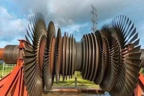
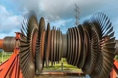
Aero Engine Blade High Pressure Turbine and Intermediate Pressure Turbine Blades Material: Nimonic 115 High Pressure & Intermediate Pressure Turbine Blades Material: Nimonic 115 Nimonic 115 is a high-performance nickel-chromium-cobalt alloy engineered... |
Send a complete technical package before requesting manufacture
A quote is only as reliable as the configuration package behind it. Before asking a supplier to price Nimonic 115 hardware, assemble the following:
1. Send the controlled drawing revision, part number, material callout, product form, heat-treatment record, customer specification, service pressure section, life limit or retirement limit, coating system, repair status, and special-process approvals.
2. Confirm whether the item is an approved production part, an approved replacement part, or a repair item. The phrase Nimonic aero engine components does not establish OEM interchangeability, so verify the governing design authority, process specification, configuration-control method, and permitted deviations.
3. Define acceptance limits for cooling-passage blockage, film-cooling-hole position, flow distribution, surface condition, balance, dimensional tolerances, and NDT indications. Identify the inspection method for each feature, such as computed tomography, borescopy, flow testing, radiography, coordinate measurement, or fluorescent penetrant inspection.
4. For intermediate pressure turbine blades, state the service pressure section, rotational speed, expected metal temperature, coating condition, vibration exposure, and required life. Attach material heat-lot traceability, mechanical results, microstructure records, coating records, and inspection requirements.
Reject any quote that names only Nimonic 115 and a price. The supplier must identify the process route, individual or batch traceability, inspection records, and configuration control.
Frequently asked questions
What should you confirm before comparing Nimonic 115 manufacturers?
Confirm the exact Nimonic 115 specification, product form, heat-treatment condition, and required material documentation. A generic reference to Nimonic aero-engine components does not prove interchangeability.
How should you match Nimonic 115 to a turbine pressure section?
Identify whether the part is a high-pressure turbine blade, intermediate-pressure turbine blade, vane, or another stage component. Compare its temperature, stress, oxidation, creep, fatigue, and erosion exposure with Nimonic 115 capability.
What manufacturing and inspection evidence should a supplier provide?
Compare casting or forging routes, CNC machining, platform and airfoil features, cooling passages, dimensional reports, surface-finish results, material certificates, and non-destructive inspection records.
Why is a capability-based supplier comparison better than a material keyword search?
A supplier that lists Nimonic 115 may not produce your airfoil geometry, cooling features, tolerances, or inspection package. Evaluate equipment, process controls, traceability, and experience with the complete part requirement.
What should you send before requesting Nimonic 115 blade or vane manufacture?
Send the latest drawing, material and heat-treatment requirements, operating location, temperatures and loads, coating details, tolerances, surface finish, inspection plan, acceptance criteria, and applicable customer specifications.