
A blisk is not simply a disk with blades attached: it is a single rotor component whose geometry, material condition and balance must remain controlled from recovered design data through final release. By the end, you will know how stainless-steel blisks are specified, machined, inspected and compared with conventional disk-and-blade assemblies, and which evidence to request from an aftermarket supplier.
Key takeaways
- Confirm the alloy, operating temperature and corrosion environment before choosing stainless steel.
- Recover the design baseline from drawings, scans, material records and inspection data.
- Control billet traceability, five-axis machining, heat treatment and distortion at every stage.
- Demand dimensional, material-integrity and balance evidence before accepting a blisk.
What a stainless-steel blisk is—and when stainless steel makes sense
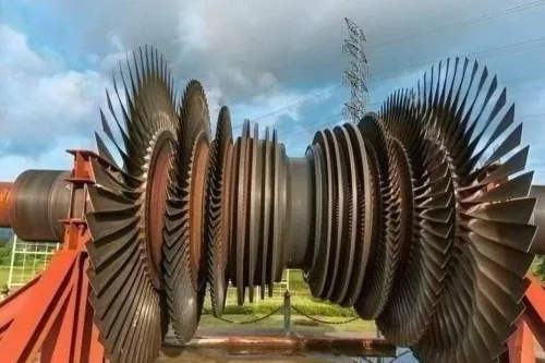
A blisk is an integrally bladed rotor: the disk and airfoils are machined as one component. It eliminates dovetails, fir-tree roots, separate blade platforms and leakage interfaces, reducing assembly variation and potential leakage paths.
The trade-off is severe: damage to one blade can become a repair issue for the complete disk rather than a simple blade replacement.
| Material | Advantages | Limits and typical use |
|---|---|---|
| Titanium | Low density reduces centrifugal loading; good specific strength and fatigue performance | Lower temperature capability; common where modern compressor weight matters |
| Aluminium | Very low density and good machinability | Lower strength, temperature capability and fatigue margin; limited special-purpose use |
| Stainless steel | Corrosion resistance, moderate-temperature strength and useful machinability | Higher density than titanium, heat generation and work hardening during machining; selected legacy, low-temperature or corrosion-resistant stages |
| Nickel-based alloy | Highest temperature capability and strong high-temperature fatigue performance | High density and difficult machining; used for hotter stages |
Stainless steel aero engine blisks are therefore not the default for modern high-pressure compressors. Select the alloy against rotor speed, centrifugal stress, temperature, corrosion environment, fatigue life and the approved engine design—not material price alone.
Specify all of the following in the purchase and airworthiness record:
- Exact grade, such as 15-5 PH or 17-4 PH
- Governing material specification and solution or precipitation-hardening condition
- Hardness range, tensile strength, yield strength and elongation
- Fatigue requirements and corrosion requirements
“Stainless” is not a production specification.
How design recovery and reverse engineering establish the production baseline
Before cutting metal, freeze the configuration: identify the engine model and stage, confirm the part number and revision, and obtain the authority-approved drawing or repair data. Record the material specification and condition, balance limits, and inspection requirements. A serviceable sample supplies measurement evidence; it does not authorize production of an aircraft part.
1. Recover primary datums from the bore and disk faces, then define the coordinate system and datum targets for machining and inspection.
2. Align scan data to those datums before reconstructing pressure- and suction-side blade profiles. Record blade twist, platform geometry, hub fillets, blend radii, and leading- and trailing-edge thickness.
3. Compare adjacent blades to identify missing or damaged geometry. Use approved design data and a documented engineering disposition to close gaps; never replace absent geometry with an unapproved guess.
4. Separate a new replacement from a repair. A replacement requires conformity to approved design and production data, while a repair requires an approved scheme defining blending or material restoration limits and the inspections that prove compliance.
5. Release a controlled digital model only after configuration review, then derive the manufacturing drawing, CNC definition, and inspection plan with revision links and serial-number traceability.
These aero engine blisk production steps establish what the machine will cut and what inspection will accept. Without that baseline, a precise geometric copy can still be an unapproved aircraft part.
Inside stainless-steel blisk manufacturing: billet, five-axis machining and heat treatment
Start with the material certificate, not the CNC program. Stainless-steel blisk manufacturing requires an approved grade, specification, heat-treatment condition and heat-lot number tied to the serialised part. Prepare the approved billet or forging, inspect the blank for size and defects, then establish bore and permitted datum surfaces before roughing the hub and disk.
| Stock form | Manufacturing consequence | Buyer’s check |
|---|---|---|
| Approved forging | Grain flow, residual stress, distortion and material allowables follow the forging route | Forging specification, supplier approval and heat-lot records |
| Solid billet or bar | Homogeneous stock does not make it equivalent to a forging | Approved material specification and process qualification |
| Unapproved substitution | Changed properties can invalidate the manufacturing and airworthiness basis | Written engineering approval before cutting metal |
Use a five-axis CNC machine for changing blade twist, narrow passages and pressure- and suction-side access. Control tool runout, cutter engagement, feed and speed, coolant delivery, tool life, workholding through the bore, tool deflection, chatter and wear. Stainless steel generates heat and work-hardens; a dull cutter can harden the surface and damage the next pass.
Rough machining precedes semi-finish and finish passes, followed by deburring, specified aging or heat treatment, surface treatment, and inspection. The approved route decides whether aging occurs before final airfoil machining to limit distortion.
Inspect thin sections, variable wall thickness, platform edges, leading and trailing edges, hub fillets and the blade-to-disk transition; a correct program can still leave profile error or a stress raiser. Complete dimensional inspection, surface and subsurface NDT, coupled rotor balancing with controlled correction areas, and release records covering revisions, nonconformances, calibration and traceability.
How manufacturers prove geometry, integrity and balance before release
Release requires traceable evidence that the blisk meets its approved geometry, contains no unacceptable defects and satisfies its balance limit—not merely a machining completion record.
1. Measure every blade against the controlled model. Record blade-to-blade profile and positional variation, airfoil thickness, leading- and trailing-edge thickness, platform form, root blends, hub fillets, bore-to-datum relationships and rotor runout.
Inspect narrow passages and obscured surfaces with probe access or scanning methods that can reach them; a clean visible tip does not prove the hidden transition is sound.
2. Use a calibrated coordinate-measuring machine, optical scanner or equivalent system with stated measurement uncertainty. The inspection program must identify its revision, datums, alignment method, sampling strategy and acceptance limits. Request calibration records, equipment standards and the program revision used for your serial number.
3. Select NDT for the suspected defect and the accessible geometry. Fluorescent penetrant testing suits suitable nonporous surfaces and detects surface-breaking discontinuities; eddy-current, ultrasonic or radiographic inspection addresses defined subsurface or volumetric concerns. Request probe access, coverage maps, calibration standards, sensitivity, indication limits and disposition rules—not just “NDT passed.”
4. Balance the coupled disk-and-blade mass distribution to the approved limit. Correct imbalance only in permitted areas using controlled material removal; random grinding can breach minimum thickness, damage the surface or reduce fatigue life.
A new replacement blisk requires conformity to approved design and production data. A repaired blisk needs an approved repair scheme covering blend limits, weld restoration, laser cladding or additive repair, followed by proof that geometry and material condition remain acceptable. A measured copy or repaired indication alone does not establish aviation approval.
How to compare a blisk supplier with a conventional disk-and-blade route
Choose an integral blisk when fewer interfaces, lower leakage risk and consistent rotor balance matter more than component-level repair. A conventional disk-and-blade assembly remains preferable when operators need rapid individual blade replacement or easier access for inspection.
| Route | Joint count and leakage | Balance, inspection and service |
|---|---|---|
| Integral blisk | No dovetail or fir-tree joints; fewer leakage paths and assembly variables | Machined mass distribution supports balance, but narrow passages restrict inspection; one damaged airfoil can make the complete disk a repair problem |
| Disk with separate blades | Multiple blade-to-disk interfaces and potential leakage or fit variation | Individual blades can be replaced, and removed parts improve access; assembly balance depends on blade matching and installation |
Compare total replacement cost, not machining price alone. A blisk can reduce assembly labour and variation, yet a single foreign-object strike can trigger full-component repair, long lead time and extensive NDT. Confirm whether the supplier can restore the airfoil under approved repair data.
For any after market aero engine for parts manufacturers stainless steel blisk production source, request:
- Material heat-lot records, approved billet or forging form, CNC and special-process qualifications, and operator and inspector competence
- Tool and program revision control, serial-numbered build records, nonconformance dispositions, NDT reports and final balance results
EASA Part 21 production or design approval is different from EASA Part 145 repair approval; check the corresponding FAA pathway. Nadcap accreditation supports confidence in covered special processes but does not replace part-specific approval. A blisk manufacturer in Munich, including BVPL Turbine Parts, deserves consideration only against this evidence, not location.
Related services
Reverse Engineered Aero Engine Blades and Blisks Blisks for Aero Engines Material : Stainless Steel Blisks for Aero Engines Material : Stainless Steel |
Reverse Engineered Aero Engine Blades and Blisks Reverse Engineered Blades by BVPL Material : Aluminium, Stainless Steel and Titanium Reverse Engineered Blades by BVPL Material : Aluminium, Stainless Steel and Titanium |
Frequently asked questions
What is a stainless-steel blisk?
It is an integrally bladed rotor machined from stainless steel, with the disk and airfoils formed as one component.
When does stainless steel make sense for a blisk?
Choose it when the required strength, temperature capability, corrosion resistance, density and machinability fit the engine location and duty cycle.
What establishes the production baseline for a replacement blisk?
Use controlled drawings, recovered design data, material specifications, inspection results and approved manufacturing tolerances to define the baseline.
What are the main stainless-steel blisk manufacturing steps?
The route includes billet verification, five-axis roughing and finishing, deburring, heat treatment, final machining and inspection.
How do manufacturers verify a blisk before release?
They check airfoil and disk geometry, material integrity, surface condition, runout and rotor balance against the approved requirements.