
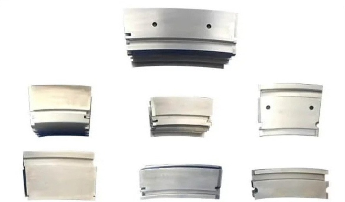
A shroud is a precisely located hot-section component at the boundary between rotating blade tips and the stationary turbine casing, but the term covers several different designs. By the end, you will be able to identify its function, distinguish it from nearby turbine hardware, recognize failure evidence, and give a supplier the information needed to quote the correct replacement.
Key takeaways
- A shroud surrounds blade tips and protects the casing from hot gas.
- Shrouds control radial clearance, tip leakage and heat transfer.
- Inspect seals and adjacent casing before blaming the shroud itself.
- Specify stage, alloy, coating, dimensions and operating conditions when ordering.
Where the Shroud Sits and What It Is
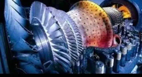
An industrial gas turbine shroud, explained in plain language, is the hardware positioned around the path of a rotating blade tip. It works with the stationary casing to maintain a controlled radial gap, limit hot gas from passing over the tip, and shield the casing from direct exposure.
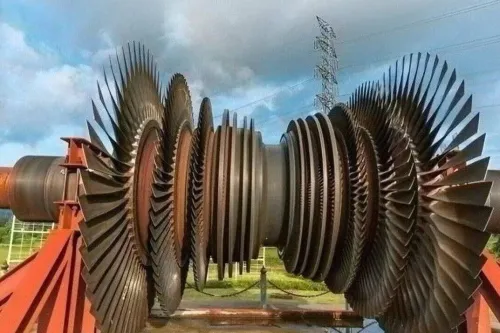
The term does not identify one universal part: it can describe a rotating shroud attached to a blade, a stationary inner ring segment, or a seal carrier with an abradable or honeycomb surface.
Nearby terms identify different hardware:
- A shroud shoe is the blade-tip projection or replaceable contact piece that forms part of the sealing interface; it is not automatically the complete shroud assembly.
- A seal segment is a stationary, replaceable section with the tip-facing sealing surface. Some drawings call this segment a shroud, while others reserve “shroud” for its support structure.
- A casing segment forms part of the engine’s outer structural boundary. It may carry a shroud, but the casing itself is not the tip seal.
- A diaphragm is a stationary interstage structure that supports internal flow-path hardware and seals; it is not simply a ring around one blade row.
- A nozzle is a stationary vane that directs combustion gas into the next turbine stage. A shroud can surround a nozzle assembly without being the nozzle.
Before ordering, match the word shroud to the engine model, module, stage, drawing number, and rotating or stationary function. That identification prevents a physically similar but unusable component from entering the repair chain.
How a Shroud Controls Clearance, Leakage and Heat
A shroud improves turbine performance by keeping the radial gap at each rotating blade tip small enough to limit leakage without creating a damaging rub. Gas crossing the tip skips the blade’s pressure-to-suction pressure difference, forms a leakage vortex, and adds stage loss; its mixing also increases heat transfer downstream.
The operating gap is not the cold-build dimension. The clearance calculation must account for:
- Rotor centrifugal growth and thermal growth
- Casing thermal growth and distortion
- Bearing movement and assembly tolerance
- Acceleration and shutdown transients
A gap that passes a room-temperature inspection can close during a hot restart. An oversized gap produces persistent leakage, reducing stage efficiency and raising the thermal load on downstream hardware.
The shroud also shields the stationary casing from direct hot-gas exposure. Cooling passages protect the shroud metal, but excess cooling air mixes into the gas path and reduces cycle efficiency; blocked, enlarged, or misplaced holes can raise metal temperature while changing leakage flow.
That balance determines hot-section durability during oxidation and thermal-fatigue cycles, as well as rub tolerance and repair cost. Across gas turbine shroud applications, the correct design is therefore an operating interface—not simply a close-fitting ring.
Which Turbine Sections Use Shrouds—and Who Needs Them
First-stage and later-stage hot-gas-path modules in frame-type industrial gas turbines use shrouds when the OEM design calls for them. The exact arrangement depends on the engine platform, such as a GE frame, Siemens Energy machine, or another OEM model.
| Equipment | Shroud arrangement | Typical buying or replacement route |
|---|---|---|
| First-stage turbine | Segmented stationary shroud around the blade-tip path | OEM, MRO provider, or power-plant owner replaces segments by stage and position |
| Later turbine stages | Stationary segments, with geometry varying by stage | Overhaul shop or approved service company matches the module and carrier interface |
| Shrouded rotating blades | Blade-integrated tip shrouds that interlock or couple adjacent blades | Gas turbine blade and vane manufacturers supply matched blade sets, not generic loose parts |
| Inlet, exhaust, diffuser, or auxiliary systems | Separate shroud or sealing hardware outside the blade-tip system | Buyer identifies the module before requesting a quotation |
The usual buyers are:
- Gas-turbine OEMs and component integrators building new engines or modules
- Utilities, captive-power operators, and fleet owners replacing damaged hot-section hardware
- MRO organizations and independent repair stations performing approved inspections, repairs, and overhauls
- Fleet operators with approved in-house repair capability
- Precision-machining suppliers producing qualified replacement hardware under controlled drawings and process approvals
A general CNC-machining capability does not establish shroud qualification. Buyers need the engine model, module, stage, rotating or stationary function, drawing number, and whether the part is an OEM replacement, approved repair, or new design.
Failure Clues: Shroud, Seal Segment or Adjacent Hardware?
Identify the part by where it sits and what moves against it, not by the damage pattern. A rotating blade-tip shroud is attached to the blade or blade assembly and travels with the rotor; a stationary shroud or seal segment is fixed to the casing and surrounds the blade-tip path.
- Rotor attachment points, blade-platform geometry and matching part numbers indicate a blade-integrated shroud. Check for centrifugal-load damage, cracked interlocks and contact marks on the rotating seal path.
- Casing hooks, retaining rails, keys or segment fasteners indicate a stationary shroud or seal segment. Circumferential rubs, missing abradable material and local gas-wash erosion support that identification.
- A honeycomb or abradable face mounted in a carrier points to a seal-support assembly rather than a complete blade shroud. The carrier may remain sound while the sealing surface is consumed.
- Nozzle vanes, diaphragm parts and casing liners have different airfoil, platform or mounting geometry. A damaged vane platform is not a shroud because it guides flow into the rotor rather than closing the blade-tip gap.
Use the engine model, module, stage, circumferential position and drawing number to resolve ambiguous terminology. “Shroud” can also describe inlet, exhaust or diffuser hardware, so a photograph alone is unsafe for identification.
Compare the removed part with the illustrated-parts catalogue and installation drawing. Confirm whether the repair instruction names replacement, weld repair, coating restoration or dimensional acceptance; a later-stage seal segment is not interchangeable with a first-stage part simply because its arc length looks similar.
What to Specify When Buying a Replacement Shroud
Fit starts with identification, not a catalogue photograph. Give the supplier the turbine OEM, engine model and frame, module, stage, drawing or part number, revision, and whether the shroud is rotating with a blade set or stationary in a segmented carrier. Also state whether you need an OEM replacement, approved repair, or new-design component.
Ask for these details before accepting a quotation:
- Material specification, heat-treatment condition, casting or forging route, and any required grain structure for the hot-section alloy.
- Critical dimensions, datum scheme, hook or rail geometry, segment gaps, rub-clearance limits, cooling passages, and allowable distortion.
- Coating system and thickness, including bond coat, hardface or abradable layer, surface preparation, repair limits, and post-coating inspection.
- Manufacturing capability for the profile: five-axis or equivalent machining, nickel-alloy cutting experience, and process controls for thin walls and sealing faces.
- Inspection records: calibrated CMM results, profile scans, coating-thickness readings, hardness or metallurgical reports, and non-destructive test results where specified.
- Traceability from raw material heat and furnace cycle through machining, coating, inspection, repair, and final release.
- Approval status, quality system, special-process approvals, and acceptance documents required by your OEM, MRO, or approved-supplier list.
For an industrial gas turbine shroud in Bengaluru, assess the same evidence you would request from industrial turbine shroud manufacturers in Bengaluru: location helps logistics, not qualification. BVPL Turbine Parts is relevant only after its process records and inspection plan match your program’s requirements.
Related service
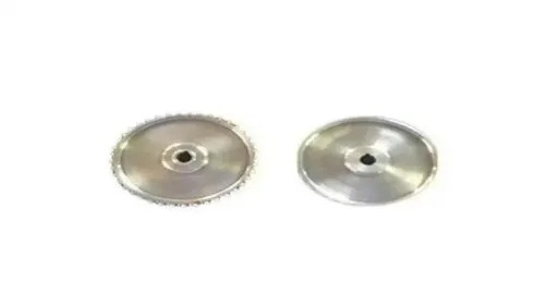
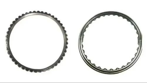
Industrial Gas Turbine Shrouds Industrial Gas Turbine Shrouds Examples of GE Gas Turbine Shrouds for Frames 5, 6, 7 and 9. We regularly manufacture these for the European, USA and Middle Eastern markets. View service → |
Frequently asked questions
What is an industrial gas turbine shroud?
It is stationary hardware around a rotating blade-tip path. It maintains a controlled radial gap, limits hot-gas leakage over the blade tip and protects the casing from direct heat exposure.
How does a gas turbine shroud control clearance and leakage?
The shroud forms the stationary boundary around the blade tips. Its radial gap and sealing features reduce the amount of gas that escapes over each tip while allowing for thermal expansion and rotor movement.
Which gas turbine sections use shrouds?
Shrouds are used around blade-tip paths in turbine stages where tip leakage, casing heat exposure and clearance control affect performance. The exact design varies by stage, engine or turbine model and operating temperature.
How can you tell whether a failure involves the shroud or a seal segment?
Check the damage pattern, rub marks, erosion, cracking, coating loss and dimensional change against the service records. A seal segment, casing feature or adjacent stationary component can produce similar clearance and leakage symptoms.
What should you specify when buying a replacement shroud?
Provide the turbine and stage identification, part number and revision, material or alloy, coating system, drawing dimensions, tolerances, attachment details, operating temperature and evidence of the required inspection or traceability records.