
A stainless steel blisk is not a collection of blade surfaces copied from an old rotor. A reliable replacement requires the manufacturer to identify the material condition, recover the airfoil and disk geometry, separate design intent from service damage, and verify the finished rotor against approved engineering limits.
Key takeaways
- Identify the stainless steel grade, heat treatment, and service condition before copying geometry.
- Scan undamaged reference areas separately from dents, cracks, and erosion.
- Convert point-cloud measurements into controlled CAD surfaces with defined datum systems.
- Verify dimensions, material condition, balance, and surface integrity before release.
What a Stainless Steel Blisk Contains That Must Be Recovered
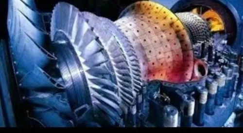
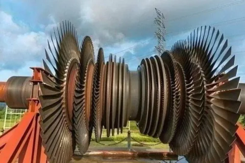
A blisk is an integrally bladed rotor: the disk and multiple airfoils form one structural component. A conventional bladed disk uses separate blades fitted into slots in a hub, so its joints, roots, and retention hardware are absent from a blisk.
For stainless steel aero engine blisks, reverse engineering means recovering the rotor’s complete functional definition, not tracing visible blade surfaces. The definition includes:
- Airfoil sections at controlled span stations
- Leading-edge and trailing-edge radii
- Platform geometry and fillets
- The disk bore, faces, datums, and balance features
- Tip-clearance relationships
- Root-free transitions where each blade flows into the disk
These features control airflow, stiffness, mass distribution, concentricity, machining access, and rotor balance. A smooth-looking surface copy can still produce the wrong rotor if it changes the bore, fillet, blade-to-disk transition, or tip relationship.
Separate the reference component, measured condition, reconstructed design model, and approved replacement specification. The reference component is the physical part presented for study; measured condition records what scanning or probing finds; the reconstructed model represents intended geometry; and the approved specification authorizes manufacture.
Do not copy damage as design. An eroded leading edge, worn tip, impact mark, oxidation, repair buildup, or scanner noise can record service history rather than intended geometry. Engineers must compare evidence, apply design judgment, and obtain approval for inferred geometry before releasing reverse engineered blisks for production.
How the Stainless Steel Grade and Heat Treatment Set the Starting Point
Before geometry work begins, identify the alloy from controlled records, not from appearance. For stainless steel aero engine blisks, the trace should lead to the engine drawing, material specification, purchase record, or approved repair document. A label reading “stainless steel” cannot establish the grade, condition, or permitted use.
1. Record the exact grade and governing specification. If the documentation names 17-4 PH stainless steel, record UNS S17400 and the applicable specification, such as AMS 5643 or ASTM A564.
2. Record the heat-treatment condition with the grade. H900 and H1150 are not interchangeable: each produces different strength, toughness, and hardness. Check the stated condition against the material certificate and confirm hardness by an approved hardness test; do not assign one universal hardness range to every blisk.
3. Separate corrosion resistance from temperature capability. 17-4 PH resists atmospheric corrosion, but its strength declines as temperature rises. Obtain the operating-temperature limit from the engine design authority, OEM material data, or an approved engineering specification.
4. Complete material identity before machining. Review heat-treatment records, perform chemical analysis when traceability is incomplete, and examine the part for sensitisation, pitting, oxidation, or other corrosion that could distort both material assessment and measured geometry.
This evidence gives aero engine blisk manufacturing a defensible starting point. If records, chemistry, hardness, and condition disagree, stop geometry reconstruction and resolve the material identity first.
How Manufacturers Capture Geometry and Remove Service Damage from the Data
Inspection starts with the original blisk mounted on functional datums, not with a freehand scan. A coordinate-measuring machine records the bore, disk faces, datum features, platforms, airfoil sections, runout, and feature locations through controlled probe access. Technicians repeat critical measurements and protect narrow edges from probe interference.
| Method | Captures well | Limitation |
|---|---|---|
| Coordinate-measuring machine | Datums, bore geometry, faces, runout, and precise feature locations | Slow on complex surfaces and blind passages |
| Optical scanning | Dense point clouds across visible airfoils, platforms, and disk surfaces | Misses occluded areas and can misread reflective or damaged edges |
| Computed tomography | Internal passages, hidden transitions, wall thickness, and inaccessible geometry | Requires suitable part size, equipment, resolution, and inspection access |
A combined method gives reverse engineered blisks a defensible geometry record when no single system sees every feature. Before modelling, technicians align datasets to functional datums and label each deviation as intended geometry, wear, erosion, impact damage, oxidation, repair buildup, or measurement noise.
They compare repeated scans, inspect leading and trailing edges, review service and repair records, and retain genuine fillets and small-radius features instead of smoothing them away.
For aero engine parts manufacturers reverse engineered for stainless steel blisks, the inspection brief should include the engine and module identification, part number, serial or batch number, drawing revision, service history, operating stage, material specification, and original component. Without that context, a worn surface can become an incorrect design feature.
How a Point Cloud Becomes a Controlled Blisk Design
A point cloud becomes a controlled blisk design when engineers replace measured coordinates with editable relationships. They section each airfoil at specified span stations, reconstruct pressure and suction surfaces, and define leading-edge and trailing-edge radii rather than copying scan noise.
The CAD model must also rebuild the platform, fillets, disk bore, disk faces, balance features, and integral blade-to-disk transitions as parametric features. Those relationships control tip clearance, concentricity, rotor stiffness, mass distribution, and tool access during machining.
| Representation | Suitable use | Failure risk |
|---|---|---|
| Point cloud | Evidence of measured condition | Cannot drive controlled production |
| Uneditable mesh | Visual reference | Hides datums and design intent |
| Parametric CAD | Manufacturing and inspection | Requires engineering decisions and approval |
Aero engine parts manufacturers reverse engineered for stainless steel blisks should preserve the design logic in the model, not export a surface copy. The model must generate a manufacturing drawing containing datums, dimensions, geometric dimensioning and tolerancing, surface-finish requirements, material and heat-treatment callouts, and revision control.
The inspection plan assigns checks to each manufacturing stage:
- Incoming material: grade, certificate, heat-treatment condition, and traceability
- Rough machining: stock, bore, disk faces, and datum features
- After heat treatment: distortion, hardness, and critical geometry
- Finish machining: airfoil sections, radii, fillets, runout, and surface finish
- Final acceptance: dimensions, balance features, mass properties, and deviations
Flag every inferred feature created from missing or damaged geometry. Obtain approval from the engine OEM, overhaul manual owner, or approved engineering authority before releasing aero engine blisk manufacturing data for production.
How the Finished Blisk Is Verified Before Release
A release decision should rest on a controlled comparison, not on the statement that a part was reverse engineered. For stainless steel blisk suppliers in Bengaluru or elsewhere, request an acceptance package built from the approved datum scheme and referenced to the original component or controlled CAD model.
1. Check the dimensional report. It should identify each airfoil section and tolerance, leading- and trailing-edge condition, platform and fillet geometry, disk-bore size, runout, concentricity, surface finish, and dimensions governing tip clearance. Confirm that the report states the measured value, allowable limit, inspection method, and drawing revision.
2. Check the rotor definition. The file should record mass, centre of gravity, moment of inertia where specified, and rotor balance results, including the required balance class. Numerical limits are not universal: the engine OEM drawing, overhaul manual, approved repair scheme, or engineering authority sets the allowable values.
3. Check material and process evidence. Require the material certificate, grade and heat-treatment condition, hardness result, heat-treatment record, and non-destructive examination results where required. The records should link the heat, serial number, machining stages, inspection stages, and inspectors to the finished blisk.
4. Check exceptions before acceptance. Every deviation from the controlled design needs an approved disposition from the responsible engineering authority; an unexplained repair, substituted material, or missing inspection record is a release hold.
A complete package contains the controlled drawing revision, CMM or scan report, material and heat-treatment records, NDE results, machining and inspection traceability, and deviation approvals. This lets a buyer assess BVPL Turbine Parts or another supplier on engineering control during aero engine blisk manufacturing, rather than on a claim about reverse engineered blisks.
Related services
Reverse Engineered Aero Engine Blades and Blisks Blisks for Aero Engines Material : Stainless Steel Blisks for Aero Engines Material : Stainless Steel |
Reverse Engineered Aero Engine Blades and Blisks Reverse Engineered Blades by BVPL Material : Aluminium, Stainless Steel and Titanium Reverse Engineered Blades by BVPL Material : Aluminium, Stainless Steel and Titanium |
Frequently asked questions
What must manufacturers recover when reverse engineering a stainless steel blisk?
They must recover the disk, airfoil, hub, platform, fillet, bore, balance, datum, and material-condition features that control fit and performance.
Why do stainless steel grade and heat treatment matter in blisk reverse engineering?
The grade and heat treatment determine strength, hardness, corrosion resistance, machinability, and the baseline condition against which the replacement is evaluated.
How are service damage and geometry captured during reverse engineering?
Manufacturers scan the part, separate intact geometry from dents, cracks, erosion, and deposits, then remove damage from the design data rather than copying it.
How is a reverse engineered blisk verified before release?
The finished blisk is checked against controlled CAD for dimensions and airfoil form, then assessed for material condition, surface integrity, balance, and required documentation.