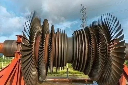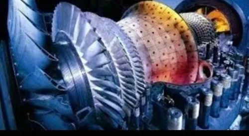

A blisk combines the rotor disk and its blades into one integrally manufactured component, removing many blade-root joints but concentrating more design and inspection risk in a single part. By the end, you will be able to judge where stainless steel is suitable, compare it with titanium and nickel alloys, specify the right blisk, and assess whether a supplier can produce and verify it.
Key takeaways
- An integral blisk removes blade-root attachments, reducing parts and assembly interfaces.
- Match stainless-steel grade and heat treatment to temperature, stress, fatigue, and corrosion demands.
- Define interfaces, balance limits, airflow geometry, and inspection requirements before design release.
- Require traceable material records, dimensional inspection, balance testing, and non-destructive examination.
What a blisk changes in a gas-turbine rotor
A blisk replaces the conventional rotor’s separate blade attachments with one integrally bladed component. In a conventional bladed disk, each blade fits into a dovetail or fir-tree root, often with platforms, retainers, and interfaces that add part count and assembly tolerance.
A blisk removes those roots and interfaces by machining or manufacturing the blades directly from the disk.
| Rotor type | Construction | Practical result | Main trade-off |
|---|---|---|---|
| Conventional bladed disk | Separate blades fitted to disk attachments | Individual blades can be removed and replaced; established repair routes | More hardware, attachment weight, leakage paths, and assembly variation |
| Stainless steel blisk | Disk and blades form one registered component | Fewer parts, continuous airfoil geometry, reduced attachment leakage, and potentially lower rotor mass | One damaged blade can require local blisk repair or replacement; five-axis machining is slow and difficult |
| Titanium or nickel blisk | Integral construction in a material selected for its temperature range | Similar aerodynamic and assembly benefits, with titanium favouring lower weight and nickel favouring hotter service | Material cost, machining difficulty, density, or temperature limits vary by alloy |
Its stainless steel blisk advantages are strongest in lower- and intermediate-temperature compressor stages exposed to humid air, contaminants, or wash chemicals. Corrosion resistance and strength can be useful there, but chloride pitting, crevices, and residual tensile stress still demand control.
The integrated rotor must be balanced after blade finishing. Airfoil mass variation and profile errors can change residual unbalance, runout, and vibration response. Stainless steel is not a drop-in substitute for titanium or nickel alloys: rotor speed, temperature, fatigue, density, coatings, and galvanic compatibility must be checked before design release.
Where stainless steel works—and where it reaches its limit
Stainless steel fits selected lower- and intermediate-temperature compressor stages because it combines useful strength, corrosion resistance, and machinability without requiring a nickel-alloy solution. The stainless steel blisk advantages are strongest where humid air, industrial contaminants, or wash chemicals threaten conventional materials.
However, 17-4 PH loses strength substantially as temperature rises, so it is not a universal hot-section material.
| Material | Temperature and strength | Density, corrosion, and practical fit |
|---|---|---|
| Stainless steel | Strong in moderate-temperature service; capability falls as temperature increases | Denser than titanium, corrosion-resistant by grade; suitable for selected compressor stages |
| Titanium | Lower density and strong specific properties in compressor service; limited by higher-temperature oxidation and strength loss | Lightweight, but surface damage, contamination, and temperature limits require control |
| Nickel-based alloy | Retains strength and oxidation resistance at the highest temperatures | Heavier and harder to machine, but normally preferred for hot turbine stages |
Stainless steel blisk benefits gas turbine manufacturers through lower part count, fewer attachment interfaces, and a practical balance between manufacturing effort and compressor durability. It is not a drop-in substitute for titanium or nickel-based blisks: rotor speed, fatigue loading, temperature, galvanic compatibility, coatings, and repair strategy must be checked together.
Chlorides, crevices, residual tensile stress, or poor surface condition can still cause pitting or stress-corrosion cracking. Use nickel-based material when the stage operates in the hottest turbine environment; choose titanium when weight dominates and its temperature limits remain acceptable.
Choose the stainless-steel grade and material condition before design release
Release the design only after fixing both the alloy and its heat-treatment condition. For many compressor blisks, precipitation-hardening stainless steels are more credible starting points than 304 or 316, which lack the required strength and dimensional stability.
| Grade and condition | Strength–toughness balance | Design implication |
|---|---|---|
| 17-4 PH H900 | Highest strength; lower toughness and stress-corrosion margin | Use for high-load, moderate-temperature stages after checking fatigue and chloride exposure |
| 17-4 PH H1025 | Lower strength; improved toughness and stability | Practical compromise for rotating compressor hardware |
| 17-4 PH H1150 | Lowest strength of these conditions; better toughness and residual-stress tolerance | Consider where damage tolerance and distortion control outrank peak strength |
| 15-5 PH or 13-8 Mo | Condition-specific strength, toughness, and corrosion performance | Select when the approved material specification and environmental data support them |
The stainless steel blisk advantages disappear if the condition does not match the duty. Rotor speed sets centrifugal stress; compressor temperature controls strength retention and dimensional growth; humid air, chlorides, wash chemicals, crevices, and tensile residual stress control pitting and stress-corrosion risk.
Put the complete material state on the purchase definition:
- Alloy, product form, chemical limits, and heat-treatment condition
- Minimum hardness or tensile properties, with grain or microstructure limits where specified
- Stress relief, aging, surface finish, passivation, and corrosion acceptance criteria
- Permitted rework route after roughing, because residual stress can move blades during finishing
Require staged machining and an intermediate dimensional check. A grade that meets a coupon tensile test can still distort when material is removed from the opposite side of the blisk.
Specify the blisk so it fits the engine and survives service
Start with the engine identity, not the alloy. State the engine model and variant, compressor stage, rotor speed range, rotation direction, mating interfaces, operating temperature, pressure, contaminants, wash chemicals, and expected duty cycles. A blisk sized for one stage is not automatically interchangeable with another.
| Definition | Specify | Failure if omitted |
|---|---|---|
| Geometry | Airfoil coordinates, twist, chord, fillet radii, platform shape, tip clearance, disk bore, flange faces, and datum scheme | Poor airflow, cutter access problems, or an interface that will not fit |
| Loads and fatigue | Steady and transient temperatures, centrifugal loads, vibratory modes, overspeed case, start-stop cycles, and fatigue-life target | Resonance, low-cycle fatigue, or an unsafe life prediction |
| Balance | Balancing axis, datum, rotational speed, residual-unbalance limit, and correction method | Rotor vibration and bearing damage |
| Damage tolerance | Initial flaw size, crack-growth method, allowable indications, inspection interval, and repair limits | A small defect becomes an uncontrolled service crack |
| Inspection | CMM or airfoil scan coverage, dimensional tolerances, fluorescent penetrant or eddy-current method, ultrasonic scope, calibration, and reporting format | Defects remain hidden or results cannot be traced |
These stainless steel blisk benefits gas turbine manufacturers only when the design definition controls the entire service life. Require heat-lot traceability, approved heat treatment, calibrated five-axis machining and inspection equipment, and documented deviation and repair procedures from an aero engine blisk supplier.
Ask for the balance report, dimensional map, NDT records, and material certificates before release.
How suppliers manufacture and verify an integral rotor
Balancing the disk before the blades are finished proves almost nothing about the completed rotor. Blade mass, airfoil deviation, and residual stress can shift the rotor response after final machining.
A controlled route starts with a traceable stainless-steel heat lot and the specified material condition. The supplier then uses stress-relieved or suitably aged stock, staged five-axis roughing, approved heat treatment, controlled fixturing, and intermediate inspection before removing the final airfoil material. This sequence limits blade movement when material is removed from the opposite side.
Ask the aero-engine blisk supplier for evidence that covers the complete route:
- Heat-lot certificates, chemical composition, hardness or tensile results, and heat-treatment records tied to the part serial number.
- Calibration records for five-axis machines, probes, coordinate-measuring machines, and airfoil inspection software.
- Airfoil reports showing measured chord, twist, thickness, leading-edge and trailing-edge form, pitch, and datum alignment against the released model.
- Non-destructive testing results, such as fluorescent penetrant inspection and ultrasonic inspection where the geometry and specification require them, plus records for any repair or deviation.
- Final rotor measurements showing datum runout, concentricity, residual unbalance, and the balance grade or acceptance method used after all blades and finishes are complete.
For gas turbine blade manufacturer blisks, inspect the deviation system as closely as the machining capability: undocumented blending can change fatigue margins. When assessing BVPL Turbine Parts, request these serialised records rather than accepting CNC capacity as proof of rotor quality.
Related services
Reverse Engineered Aero Engine Blades and Blisks Blisks for Aero Engines Material : Stainless Steel Blisks for Aero Engines Material : Stainless Steel |
Reverse Engineered Aero Engine Blades and Blisks Reverse Engineered Blades by BVPL Material : Aluminium, Stainless Steel and Titanium Reverse Engineered Blades by BVPL Material : Aluminium, Stainless Steel and Titanium |
Frequently asked questions
What does a blisk change in a gas-turbine rotor?
A blisk combines the disk and blades into one integral component, removing separate dovetail or fir-tree attachments, retainers, and assembly interfaces.
Where does stainless steel work in a gas-turbine blisk?
Stainless steel suits blisk stages whose temperature, centrifugal stress, fatigue, oxidation, and corrosion requirements remain within the selected grade and material condition’s limits.
What should you specify before releasing a stainless-steel blisk design?
Specify the stainless-steel grade, heat treatment, mechanical requirements, blade and disk geometry, shaft interfaces, balance limits, surface condition, inspection plan, and traceability documents.
How should a supplier manufacture and verify an integral rotor?
Ask for controlled CNC machining, material traceability, dimensional inspection, runout and balance results, surface-finish checks, and non-destructive examination suited to the component.