
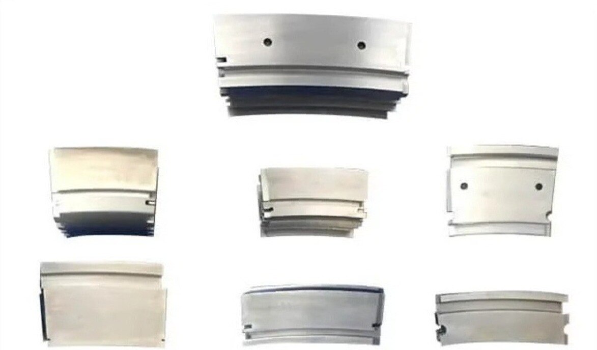
A shroud is a stationary hot-section boundary whose fit depends on far more than a matching blade-tip radius. By the end, you will be able to identify the shroud type you need, verify industrial gas turbine shroud fit, compare supply and repair options, and decide whether your manufacturing capability supports the work.
Key takeaways
- Confirm shroud type, dimensions, coating, material, and attachment method before quoting.
- Match the replacement to the engine model, stage, drawing revision, and operating configuration.
- Treat rubs, cracks, oxidation, and distortion as evidence of clearance or system problems.
- Make shrouds in-house only when inspection, tooling, materials, and quality controls are ready.
What a shroud does—and which shroud part you are actually buying
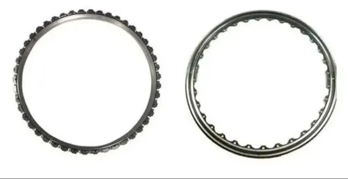
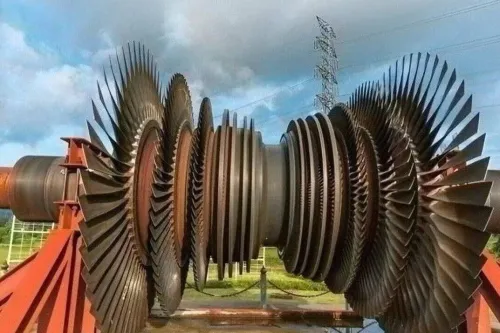
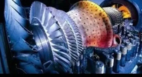
An industrial gas turbine shroud creates the stationary outer boundary around rotating blade tips. Its inner surface holds the designed tip clearance, reducing the pressure-driven flow that would leak over each blade and waste combustion energy. It also shields the casing from hot gas and blade-tip rub damage.
Its industrial gas turbine shroud uses therefore include sealing, thermal protection, and controlled rub tolerance.
The name on a quote does not identify the deliverable. In gas turbine shroud applications, “shroud segment,” “shroud block,” “outer air seal,” and “blade-ring segment” can describe different OEM-specific parts.
| Part | What it is | What you are buying |
|---|---|---|
| Casing-mounted shroud | The structural stationary part attached to the casing or carrier | A complete load-bearing segment with attachment features |
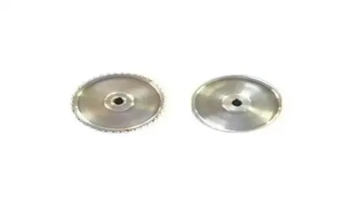
| Shroud shoe tile | A replaceable gas-path-facing insert fitted into a carrier | The tile or shoe only, not necessarily its support |
| Segmented ring | A circumferential assembly made from multiple stationary segments | One segment or the complete ring arrangement |
| Abradable blade-tip seal | A sacrificial coating or liner designed to wear during a controlled blade rub | The sealing layer, not automatically the shroud structure |
A blade-tip seal is therefore not interchangeable with a complete shroud. Before quoting, confirm whether the requirement covers the carrier, tile, coating, cooling passages, joints, and attachment hardware. A matching inner CAD surface still fails if the casing datums, segment joints, or hot running clearance are wrong.
Use this industrial gas turbine shroud fit checklist before quoting
A nominal CAD match is not enough: industrial gas turbine shroud fit depends on the engine configuration, attachment interfaces, coated surface, and hot running clearance. Confirm the controlled OEM drawing before pricing tooling or machining.
- Identify the OEM, engine frame, stage number, material condition, coating system, and approved repair scheme.
- Record clockwise or counterclockwise orientation, segment position, segment-to-segment joints, and casing or carrier datums.
- Measure the gas-path profile, blade-tip radius, axial length, radial height, seal lands, and mating casing geometry.
- Specify bolt holes, hooks, slots, keys, retainers, cooling-air passages, and every attachment datum.
- State coating type, finished thickness, adhesion requirement, masking limits, and whether dimensions apply before or after coating.
- Define cold installation clearance and hot running clearance, including allowances for rotor growth, casing growth, thermal gradients, and rub tolerance.
| Check | Evidence to quote against | Fit failure if missed |
|---|---|---|
| Frame and stage | OEM drawing, revision, and stage identifier | Wrong radius, loading, or attachment pattern |
| Orientation and position | Clocking mark and segment location | Joints or cooling passages do not align |
| Attachment | Datum scheme, bolt or hook dimensions | Segment will not seat or retain |
| Coating | Specification, thickness range, and inspection method | Coating changes the gas-path contour |
| Clearance | Cold and operating targets with measurement points | Rotor growth causes rubbing or leakage |
Ask whether the supplier will perform a first-article fit check, fluorescent-penetrant inspection, dimensional inspection after coating, and cooling-flow verification where applicable. A part that matches the nominal surface but misses these interfaces is not interchangeable.
Demand records that prove the replacement matches the intended configuration
A supplier packet is incomplete without the controlled drawing and revision that define the intended configuration. Gas turbine shroud buyers should require the engine OEM or approved repair source to identify the frame, stage, segment position, orientation, attachment datums, material, coating, repair limits, and acceptance criteria.
Request these records before approving production:
- A drawing or model showing hook, bolt, slot, seal, cooling-hole, and datum geometry, with revision history.
- A material certificate naming the alloy, heat number, processing condition, and applicable material specification.
- A coating certificate stating coating type, process, thickness range, bond or adhesion result, and inspection method.
- A dimensional inspection report tied to the drawing revision, including coated gas-path radius, axial and radial dimensions, attachment features, and edge conditions.
- Fluorescent-penetrant inspection results, plus radiography, ultrasonic testing, or cooling-flow data when the specification calls for them.
- First-article, trial-fit, or fixture evidence proving the segment seats against the mating casing without forced alignment.
Compare the supplier’s evidence against the approved configuration, not against a worn sample alone.
| Record | Compare | Reject or investigate when |
|---|---|---|
| Controlled drawing | Revision, datums, stage, orientation | Any field is missing or superseded |
| Material certificate | Alloy, heat number, condition | Heat cannot be traced to the part |
| Inspection report | Uncoated and coated dimensions | Report omits coating growth or datum references |
| NDE record | Method, acceptance level, indication map | Results are unsigned or detached from the serial number |
API 616 can frame procurement for petroleum and chemical service, but it does not replace the turbine OEM’s dimensional and inspection requirements.
Read shroud damage as a system warning, not a cosmetic defect
Determine wear by comparing cleaned hardware with the approved drawing, stage-specific limits, and prior inspection records—not by judging its color. In gas turbine shroud applications, measure the coated gas-path profile and running clearance against the specified blade-tip radius.
A shroud shoe tile for turbines can look intact while its coating, wall thickness, or attachment has already fallen outside the repair limit.
- Measure remaining wall thickness and segment distortion; low wall or a changed radius reduces future repair margin.
- Inspect the gas-path surface for erosion, hot corrosion, oxidation, coating spallation, and localized rub tracks.
- Use fluorescent-penetrant inspection on hooks, rails, cooling holes, and other stress-concentrating features; a crack at an attachment can make the segment unserviceable.
- Check blade-tip and vane evidence beside the shroud; uniform rub marks suggest clearance loss, while isolated marks point toward rotor eccentricity, casing distortion, or local misalignment.
- Compare adjacent segments and temperature-monitoring records; uneven deposits, burning, or coating loss can indicate a temperature spread rather than simple wear.
Treat the pattern as a system warning. Repeated blade-tip rubs can signal vibration, bearing or rotor alignment problems, while damaged vanes can redirect hot gas into one shroud sector.
A repaired surface that restores dimensions but leaves poor attachment integrity or uncertain coating adhesion can fail again during the next run, turning a manageable inspection finding into an unplanned outage. Preserve the removed part and its position so the failure analysis follows the hardware, not just the symptom.
When should a blade and vane manufacturer make shrouds instead of buying them?
Airfoil experience alone does not make a company ready to produce shrouds. Gas turbine blade and vane manufacturers should make the switch only when they can control the stationary segment’s interfaces, cooling behavior, coating, and complete configuration—not just its gas-path profile.
A manufacturer is ready to produce or qualify shrouds when it can demonstrate:
- Controlled drawings tied to the turbine frame, stage, segment position, orientation, and casing interface
- Hot-section materials and heat-treatment controls for the specified alloy, including traceable mill certificates
- Machining or forming processes for hooks, bolts, carriers, joints, slots, and other attachment features
- Inspection of radial and axial dimensions, blade-tip radius, joint fit, coating thickness, and running-clearance features
- Qualification of film-cooling holes, impingement passages, brazed inserts, or cooling slots when the design includes them
- Coating process control, adhesion checks, and repair limits for hardface or abradable surfaces
- A documented fit-up, dimensional, and flow-test plan that matches the OEM drawing and acceptance criteria
The deliverable also matters. Gas turbine shroud buyers must state whether they need a complete casing-mounted segment, a replaceable insert, or shroud shoe tiles for turbines; each requires different tooling and inspection.
API 616 can guide a petroleum-service procurement, but it does not define a universal shroud geometry. BVPL Turbine Parts, for example, should be assessed by the same evidence: drawing control, material traceability, cooling validation, coating records, and repeatable inspection results. Buy instead when those controls are absent.
Related products
 | 1. Industrial Gas Turbine Shrouds, Shroud Shoe Tiles, Nozzles and Diaphragms Industrial Gas Turbine Shrouds BVPL Turbine Parts manufactures precision industrial gas turbine shrouds, shroud shoe tiles, nozzles and diaphragms designed to improve turbine... View product → |
 | Gas turbine components manufacturer Industrial Gas Turbine Shrouds, Shroud Shoe Tiles, Nozzles and Diaphragms BVPL Turbine Parts manufactures precision industrial gas turbine shrouds, shroud shoe tiles, nozzles and diaphragms designed to improve turbine... View product → |
Frequently asked questions
What does an industrial gas turbine shroud do?
It forms the stationary outer boundary around blade tips, controls tip clearance, limits leakage, and protects the casing from hot gas and rub damage.
What should gas turbine blade and vane manufacturers check before quoting shroud work?
Check whether the part is a full ring, segment, shroud shoe, or tile, then confirm dimensions, stage, material, coating, attachment features, and drawing revision.
Which records prove that a replacement shroud matches the intended configuration?
Request the engine and stage identification, approved drawing revision, part number, serial or batch traceability, material certificate, coating records, inspection results, and repair history.
What can shroud damage indicate?
Rubs, cracks, oxidation, erosion, and distortion can indicate incorrect tip clearance, rotor movement, casing distortion, cooling problems, foreign-object damage, or overheating.
When should a blade and vane manufacturer make shrouds instead of buying them?
Make them when you have the required material and coating controls, tooling, dimensional inspection, traceability, and production volume; buy them when those capabilities or records are unavailable.