
A pressure-stage finding is not a repair decision: first identify the exact vane row, spool, material, configuration, and operating symptom. By following the evidence from engine data through inspection, dimensional comparison, approved limits, and documented disposition, you can separate an aerodynamic disturbance from a damaged or unserviceable component.
Key takeaways
- Confirm the vane row and part number before diagnosing pressure-stage damage.
- Separate high-pressure faults from low-pressure damage using location and trend data.
- Compare findings with the approved maintenance manual limits before disposition.
- Escalate unclear damage for engineering review instead of guessing at repairability.
Identify the Vane Row Before Diagnosing the Pressure-Stage Problem
Identify the affected vane from controlled records, not from the phrase “pressure-stage problem.” Start with the engine model, engine parts catalogue, component maintenance manual, part number, vane row, and inspection record. Confirm whether the part is an inlet guide vane, fixed stator vane, variable stator vane, rotor blade, or turbine nozzle.
| Component | What to verify | Why it matters |
|---|---|---|
| Inlet guide vane | Front location and row designation | It may be outside the numbered compressor stages |
| Fixed stator vane | Manual-defined row and spool | Stage numbering differs between engine models |
| Variable stator vane | Actuator, pivot, and rigging records | Setting errors can mimic airfoil damage |
| Rotor blade | Rotor row and blade serialisation | A rotor finding is not a stator-vane finding |
| Turbine nozzle | Turbine module and nozzle stage | Turbine terminology and materials differ from compressor terminology |
The manual’s stage numbering controls. Verify the spool and material specification before concluding that an aluminium part belongs to the high-pressure compressor; aluminium commonly serves cooler compressor-front locations, while later rows may use titanium or steel. Turbine hardware uses higher-temperature materials.
As pressure ratio and temperature rise through successive compressor stages, identify whether the finding belongs to a low-pressure compressor row, high-pressure compressor row, or another assembly. That check is essential when aero engine parts manufacturers diagnose aluminium vane pressure stage problems or investigate high pressure aluminium vane problems.
Record these identifiers before inspection:
- Clock position, row number, part number, serial or batch number
- Fixed or variable configuration and adjacent-row condition
- Approved drawing, controlled master, engineering order, or matched-set requirement
Never compare an unavailable original with a generic vane.
Separate High-Pressure Vane Faults from Low-Pressure Vane Damage
An isolated sharp notch on a high-pressure compressor vane deserves more attention than its size suggests: it can concentrate stress, change incidence, crack the airfoil, and increase downstream rotor loading. Low-pressure damage more often reflects inlet exposure across many vanes, so map the complete row before judging one conspicuous mark.
| Stage | Damage pattern | Operating symptoms and checks |
|---|---|---|
| High-pressure compressor | Leading-edge erosion, foreign-object dents, sharp notches, raised material, tip or platform damage, fretting, bushing wear, cracks, distortion, corrosion, coating loss, or blocked airflow passages | Compressor-pressure loss, exhaust-gas-temperature change, surge or stall, vibration, reduced thrust, or downstream damage. Check contour, throat area, vane setting, platform contact, and clearances. |
| Low-pressure compressor | Broad impact marks, sand or dust abrasion, trailing-edge deformation, platform cracking, rubbing, oxidation, corrosion, vibration damage, or debris ingestion | Gradual efficiency or thrust loss, vibration, contamination, and abnormal acceleration. Compare the full row with adjacent vanes for repeated exposure or distortion. |
A polished pressure-side band or transfer material is not automatically cosmetic damage. Check rub direction, circumferential pattern, mating rotor evidence, runout, and clearance records; the cause may be rotor-to-stator interference, a loose bushing, casing distortion, or vane movement.
Compare the affected vane with adjacent vanes to separate an isolated event from a row-wide or fleet-wide pattern. Review recent maintenance, compressor washes, bird or debris strikes, overspeed, overtemperature, and vibration reports before replacing the first visibly damaged vane. Oil or metal contamination and visible cracking require escalation.
Use Trend Data, Borescope Evidence, and Targeted Inspection
Confirm causation in sequence: correlate the engine symptom with one spool, one stage, and one vane row before removing parts. For aeroengine vane troubleshooting in Texas, use the engine trend record rather than a single post-event reading.
1. Review compressor pressure, exhaust-gas temperature, vibration, acceleration, surge or stall history, and recent operating events. Isolate the affected spool and pressure stage, then compare its trend with adjacent stages and previous stable runs.
2. Examine the original borescope images for impact direction, crack indications, erosion pattern, blocked passages, rub marks, and downstream debris. Preserve those images before cleaning or polishing; a pressure-side mark can reflect rotor interference, a loose bushing, or casing distortion rather than a vane-only fault.
3. Perform visual and borescope inspection for accessible damage. Use dye-penetrant testing for accessible surface-breaking cracks and eddy-current testing for near-surface flaws in conductive aluminium only when probe access, frequency, calibration standard, and geometry support the method. Magnetic-particle inspection is not a general method for aluminium.
4. Measure the vane against the exact approved drawing: chord, thickness, leading-edge radius, tip clearance, platform fit, pivot or bushing diameter, angular setting, twist, bow, runout, and variable-stator rigging or linkage backlash. Verify material, alloy, temper, heat treatment, coating, and hardness only when maintenance data require it.
5. Do not treat one NDT result as proof of serviceability. Record the method, calibrated equipment, inspector, date, clock position and row, feature type, and measured result.
Apply the Approved Limits and Build a Defensible Disposition
A disposition starts with approved data, not a visual impression or generic aluminium blending practice. Low-pressure aluminium vane damage and high-pressure aluminium vane problems require limits tied to the engine, row, alloy, revision, and repair history.
1. Obtain the current engine or component maintenance manual, structural repair manual or repair scheme, applicable FAA airworthiness directives, engine manufacturer service bulletins, and customer or military instructions. Verify each revision before applying limits for dent depth, edge-radius loss, twist, bow, tip clearance, crack length, material loss, minimum thickness, coating loss, or repair geometry.
2. Release the vane as acceptable only when every applicable limit is met and no independent rejection condition exists. A vane can meet dimensions and still fail because of a crack, corrosion, missing traceability, or prohibited prior repair. Check galvanic or crevice corrosion where aluminium contacts bushings, fasteners, coatings, or other dissimilar metals.
3. Approve repair only when the controlled data specify material removal, blend shape, heat-treatment restrictions, coating, NDT, balance or mass control, and post-repair checks. Removing enough material to eliminate a defect can also reduce airfoil contour, stiffness, or minimum thickness.
4. Quarantine suspect parts and open a nonconformance record when the condition is outside the stated limits. Stop and escalate to the OEM or approved design organisation when the data do not define the condition; that organisation can impose stricter limits than a generic material rule.
5. Preserve serial or batch traceability and record calibrated equipment, inspector identification, date, method, photographs, borescope images, datum scheme, measured values, and disposition authority. Keep the inspection finding separate from the approved return-to-service decision.
Choose Repair, Replacement, or Engineering Review Without Guessing
Replacement is more practical when approved repair data are unavailable, material loss is extensive, airfoil geometry is distorted, traceability is missing, or a matched vane set is affected.
| Option | Disposition | Use it when |
|---|---|---|
| Release | Return to service | Current approved data support acceptance after checking profile, surface finish, angular setting, clearances, balance, and vane-to-vane matching. |
| Approved repair | Send to an authorised repair source | The damage is defined by the repair scheme, including blend limits, NDT, coating, heat treatment, and post-repair inspection. |
| Engineering review | Hold and escalate | The condition falls outside the repair scheme or the data do not define its acceptance. |
| Replacement | Install a controlled, traceable part | Repair data are unavailable, geometry or minimum wall is lost, or row matching cannot be restored. |
Do not substitute an aluminium alloy, temper, coating, steel, or titanium route. Density, temperature capability, corrosion behaviour, repair controls, and stage suitability differ. Reverse engineering requires authority to reproduce, complete geometry, known alloy and heat treatment, traceability, and approval for every design change.
For aeroengine vane troubleshooting Texas, provide the engine model, part number, serial or batch number, vane row, photographs, borescope images, dimensions, operating symptoms, and requested disposition. Confirm the supplier or repair station has the required quality system, calibrated inspection capability, competent personnel, traceability, ratings, and approved scope.
BVPL Turbine Parts can support controlled inspection, repair-feasibility review, replacement manufacture, and technical documentation; manufacturing capability alone does not diagnose an in-service failure or authorise return to service. That control is why aero engine parts manufacturers diagnose aluminium vane pressure stage problems against FAA, OEM, customer, military, or power-generation requirements—not Texas location alone.
Related items
Aero Engine Blades and Vanes High Pressure and Low Pressure Aeroengine Vanes Material: Aluminium Alloy High Pressure and Low Pressure Aeroengine Vanes Material: Aluminium Alloy |
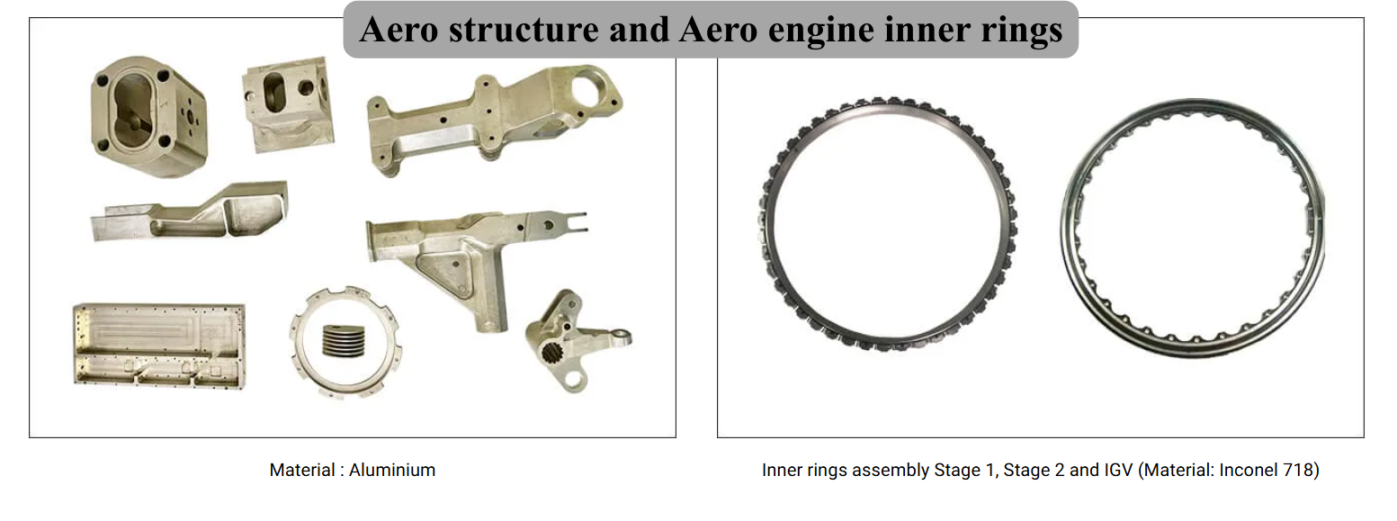 | Precision Components Manufacturer Aero structure and Aero engine inner rings BVPL Turbine Parts manufactures precision aero-structure components and aero engine inner rings used in critical aircraft and gas turbine assemblies. View product → |
Frequently asked questions
How do you identify the affected aluminium vane before diagnosing a pressure-stage problem?
Use the engine model, engine parts catalogue, component maintenance manual, part number, vane row, and inspection record. Confirm whether it is an inlet guide vane, fixed stator vane, variable stator vane, rotor blade, or turbine nozzle.
How can you distinguish high-pressure aluminium vane problems from low-pressure vane damage?
Confirm the vane row first, then compare its location with engine trend data, borescope evidence, and targeted inspection findings. Do not classify damage from the phrase “pressure-stage problem” alone.
What evidence should support an aluminium vane disposition?
Keep the inspection record, borescope images, measured damage dimensions, trend data, part identity, and the applicable approved maintenance manual limits together.
When should you choose engineering review instead of repair or replacement?
Request engineering review when the damage is outside published limits, the vane identity is uncertain, inspection evidence conflicts, or the approved data does not define the condition.
Related items
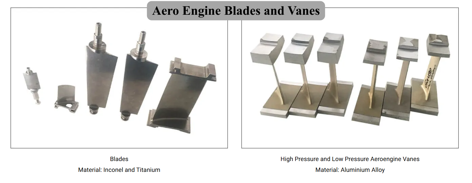 | Precision Components Manufacturer BVPL manufactures precision aero engine blades and vanes used in compressor and turbine stages of gas turbine engines. View product → |
 | Precision Components Manufacturer BVPL manufactures precision aero engine blades used in compressor and turbine stages of gas turbine engines. View product → |
Reverse Engineered Aero Engine Blades and Blisks Blisks for Aero Engines Material : Stainless Steel Blisks for Aero Engines Material : Stainless Steel |
Reverse Engineered Aero Engine Blades and Blisks Reverse Engineered Blades by BVPL Material : Aluminium, Stainless Steel and Titanium Reverse Engineered Blades by BVPL Material : Aluminium, Stainless Steel and Titanium |